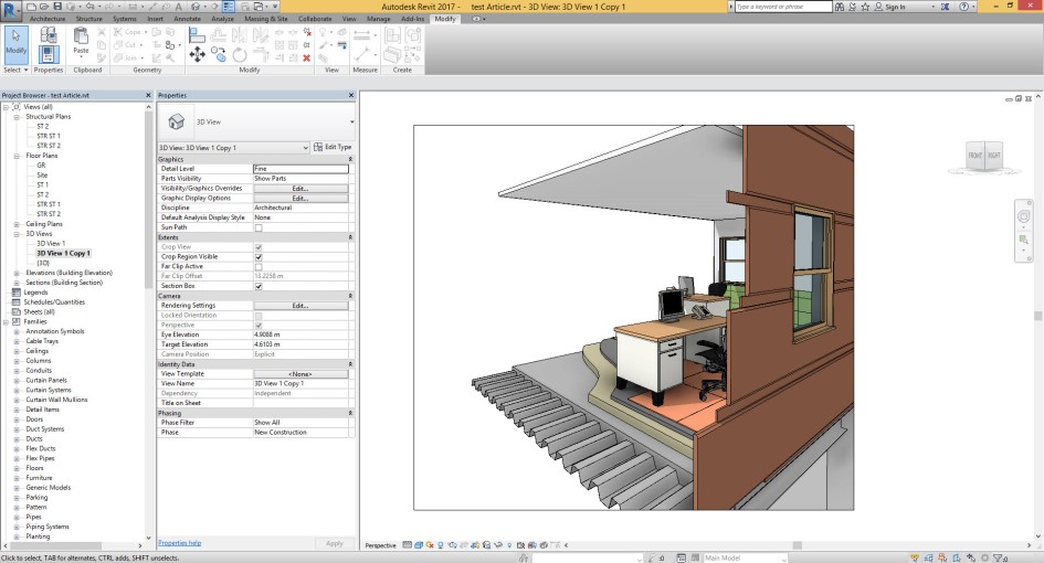
Addressing issue for Level and Grid Bubble size in different view scale?!

Hope you all are doing well!

Let’s address another issue that we usually face in our projects,

Most probably you have faced this issue before, imagine you are in the elevation or plan view and you need to change your view scale from 1:100 to something like 1:200 or 1:50, your grids and level symbols will not be presented with the proper size. They are either interfering with each other or quite small.

There are some workarounds, like design options or using separate link files for different scales. And I would say each of those workarounds will cause other issues, such as productivity and flexibility.

In the following video I will demonstrate how you can address such cases in your projects,

Hope you like it,

Behzad

Control Room Separation Lines across different Disciplines

Hi again,

Tonight i want to share another tricks which i shared in BiLT ANZ 2018,

Let’s solve one of the big issue and answer to this question, How we can control Room separation lines in Link file, when we are sharing model across different disciplines?

This is one of the biggest request from M&E people, when they are creating space in M&E file they need to define their spaces with freedom and without any restriction from Archi layout.

You can see one example in below.  in left side we have Room separation lines, which you can see with red color.


Regarding to Archi discipline for this building we have separate area for manager, reception, counter and lobby. And the way they are defining this separation is according to furniture placement, different material or partition system.

But maybe for M&E, all of this area are part of one space and no need to define separate space for each portion.

Now if we go for M&E file and make try to define Space in according to Archi Layout, this will not be possible.


Go to Archi Model and make try to define new Phase, you can call that “Room Separation Line”


Select all Room Separation line from model and after that for demolition phase, define Room Separation Line.

Yes just this, make save your file and go to M&E file, make delete all Space that you have for Manager, lobby, etc.  You should do it with Space schedule and select those space that you want to delete and make them delete from schedule.


Now if you retry it again still you can see same effect and you cannot make one space for all area.

Select your archi model link and go to Edit Type from properties panel. In Edit Type dialogue box go for Phase Mapping and change phase mapping system like below picture.

Everything is set up now and you can define new Space without any limitation from archi room separation line.


I hope you enjoy and this could help you for managing your project,

I received comment, trick was very simple, perhaps it is. 🙂

Revit is much simple than we think and in most of the time we can solve issues without Dynamo and scripting,

Take care,

Behzad

ReInvent Revit Users!

Since around 15 or 16 years, i starts my journey with Inventor and i was joying to work with this software. One of the best software for manufacturing and construction stage in the market.

Also,  when first time i starts to work with Revit, i found lot’s of familiar tools and icons. Which is common in Autodesk platform. Step by step after i start with Revit journey, i understood in many parts logic and the way we are defining parameters, doing modeling, assembling elements, defining rules, providing drawings is same with Revit.

In market, every time and every where i meet different Architects or Engineers, who were very interested to learn one software for construction stage or for providing construction details for different products or complex shape that they designed.

But every time sort of concern or doubt about manufacturing software make them disappointed to learn anything about this category.

In next April, i will deliver one talk in BiLT Asia 2018 “ReInvent Revit Users” and i will show to all, how with 2 hour you can become Inventor User.

If you are currently Revit Users and you want to become Inventor Users in 120 minutes this session is for you.

You can receive more information from below link:

http://www.rtcevents.com/bilt/asia18/

See you all, in #BiLTASIA 2018


Top Ten Speaker in BiLT Asia 2017

That was my first experience of BiLT Asia 2017,

I become one of the Top Ten Speakers in this event ( Rank 8 ) and i should say tank you to all Speakers for what you are doing for sharing your idea and making this event more valuable year by year.

Also I should say thank you to BiLT Committee for what they did for preparing this great event and gave me this chance to be Speaker for this.

I was very lucky because i meet many great and knowledgeable people.

http://www.rtcevents.com/blog/?p=7460&utm_source=rtcevents&utm_medium=email&utm_campaign=globalnews20170627

I should say Thank you to Wesley Benn, Phil Lazarus, Richard Kuppusamy, Chris Needham, Phil Read,  Heidi Lam.

And also i should say thank you DP Architect and my two friends Hui Min Chan and Kelvin Tam for Supporting me.

And i hope to be speaker in next BiLT Events.

Big secret in AU Session ; How we can make active/deactivate Room separation line in Revit!!!???

It’s become around 7 years ago when for first time i start to make link from Archi model into Revit MEP and i found some road blocks , many of those difficulties was solved after i did many projects and many of them was remained.

Now i want to show you how you can make turn on/off Room separation line from Archi Link model in MEP discipline and important things is when you are making turn off you can create your space without any limits that is coming from Archi Separation line.

As you can see in below picture we have simple plan with Room Separation line in Archi model.


In below picture you can see after i make insert Archi model in MEP project, still i can see Room Separation lines and if i try for create any room or space i will receive affect from room separation lines.


And now i make turned off all room separation line from Archi Link and then i make new space according to Space separation line in MEP.


I will share with you about this tricks in the future but for now i need your help.

Currently i sent proposal for AU University 2017 and i need your vote. If this type of tricks are interesting for you please go to the below website and make search for this two title:

  1. Revit : Golden Tricks for save your life!
  2. Re Invent Revit: Inventor for Revit Users!


http://au.autodesk.com/speaker-resource-center/call-for-proposals/voting


Good Luck

Best.

Re Invent Revit: Session 4, 2D Sketch assignment

I think without assignment we will not achieve to anything, hence I thought maybe i should prepare some record from 2d Sketch environment. In some part of this records I will show you how we can do something in Revit and how we should do that in Inventor.
You can watch records in below, also i should say in next few days i will make more record about 2d Sketch.


After you tried for this, if you need any help just ask I will tell you how you can make fix problems.
Good luck.

AU Proposal for 2017 : “Re Invent Revit”

Dear All,

After many years work with Autodesk software’s and share my knowledge with other people in different community and learn from community know i want share my idea with you through the AU University 2018 in Vegas.

I wrote three proposal and this on is about Inventor and Revit, anybody is currently Revit user i really believe he/she could be next Inventor user just with simple mindset from Revit and 3d Modeling, you will become next generation of Inventor users.

Please take a look to au.autodesk web site from below link and read my class description, if you like that then vote for that in AU website.

http://au.autodesk.com/speaker-resource-center/call-for-proposals/voting

If you need more info about me just check my Linkedin Account or you find more info in my blog.

https://www.linkedin.com/in/behzadmeskini/

https://dddmodeling.wordpress.com/about/


I need you vote, please support me.


Best Regards,

Behzad Meskini

Re Invent Revit: Session 3, 2D Sketch

Now you know about many thing in Inventor, we can go for first modeling feature.

Like Revit or any other software, when you want to make extrude at first you need to have one 2d Sketch and after that you can go for Extrude command.

As you can see we have separate icon for create 2D Sketch.

But we have two major difference here:


  1. In Revit you don’t have separate command for create 2d Sketch and each time you are hitting Extrude command you will go to the Sketch environment and you can have access to 2d Tools like line, circle, rectangle and etc. But in Inventor you should have 2D Sketch at first and then you can go for Extrude. Take a look to the above pictures.

2. Another thing is about the Work Plane , in Revit if you are in Reference Level, Current Work Plane is Reference Level and if you are in Front/Back or Left/Right view you can use Set Work Plane command to make set one Reference Plane for 2D Sketch, but in Inventor after or before you run 2D Sketch tool you should select one Origin or User Work Plane or like in Revit You can select One Flat Surface for create new 2D Sketch.

In Inventor you have many tools for create 2d Sketch and honestly in some case you can’t find any equivalent tools in Revit but still you can find many similar tools and workflow, I can give you short brief about this tools in Inventor and you can read about that in below.

Note : In Revit we hadn’t any 2D Constrain until to Revit 2017, in this version you can see only new item and that one is about Tangent Constrain for Arc shape and you can see relevant picture in below:


Note : In Revit you can’t use Array Command for make Array from elements that we have in 2D Sketch.

Option Bar:  Before of short brief i should explain about Option Bar in Revit and equivalent item in Inventor, as you know after we run any tool in Revit we can find some option according to that tool in Option Bar i want to explain about this with two simple example :


1. Revit : Copy = Inventor : Copy  : As you can see in Revit you can run Copy command at first and after make select your objects, press Enter and then you will receive some option in Option Bar , but in Inventor after you run Copy command you can receive dialogue box regarding to the Copy and all option are appearing in dialogue box.


2. Revit : Offset = Inventor : Offset   ; As you can see for Offset Command After we run this tools in Revit we can see different option in Option Bar but in Inventor after we run Offset command we are not receiving any dialogue and with Right Click we can see some option like Loop Select or Constraint Offset and also if you make click at any objects you can define value for offset tool.

Note : In 2d Sketch environment we have 2d constrain which could be little strange for anyone who hasn’t any experience with this. But if you are that type of user in AutoCAD who is using Constraint then you can find many similarly way for apply 2d constrain.

In Inventor you can see after you run move command you will see Move dialogue box and then you can select your objects with selection button and define two point with location.

Note : All tools for draw are very similar to Revit.

Note : All tools for Modify are very similar to Revit


2d Rectangular pattern in Inventor : In Revit you can make duplicate 3d elements with Array Linear, the biggest problem is you can define one axis for this but here in Inventor you can define two axis for make array from 2d elements and actually this tools is very similar like AutoCAD Rectangular Array.

2d Circular pattern in Inventor : In Inventor we can make pattern from 2D Elements with Circular Pattern and the only thing you need to define here is about the object for duplicate and Center of array, also this tool is like AutoCAD.


Inventor Mirror : Take a look to above picture

Note : In Industrial Software like Inventor we have different color for 2d Sketch elements and also if we have any sketch with all dimension that we need to make control for size and location of sketch, we can call that Fully Constrain. I will show you one simple example in below pictures and in the future we will learn more about this:


You can see one Rectangle with all dimension as full constrain and another Rectangle without dimension as a free shape. pay attention to the color.

As we said we will discuss about this in the future.

Good luck.

Re Invent Revit : Session 2

Ok, Second Session is about modelling procedure, after short explanation in “Session 1″for file type in Inventor and compare that items with Revit now it’s the right time for start new model in Inventor.

But before we start to talk about this item, i should tell you one things about what we are doing usually in Revit and what we should do in Inventor.

Every time i’m teaching Revit, i’m explaining about Project Environment at first then after that i’m going for Family.

The point is in Revit because of two thing:

  1. Template for create new projects. (In every project template, we have different type of Wall, Floor, Roof, Ceiling, Stairs, Railing, as system families and also we have different type of Loadable family like Furniture, Columns, Beam, Door, Windows)
  2. Default Content Library. (We can find many different type of Furniture and Column, Door, Window, Tag, … etc that are very useful for start new project)

we can start from project.

Just for one moment imagine this in Revit, you starting new project, but you don’t have any family?!? I’m talking about all family like Systemperature Family, Loadable Family or Model-In Place Family.
Now what you should do?!?! Yes, you should create all things by your own.

—————————————————————————————————————————————————————————————–


Note: If we try to make compare as this way it’s not fair , because I can say in Inventor we have biggest default content in the world for industrial usage. Pay attention, Industrial. It’s not Door or Window it’s Screw, Nuts, Washers, Pin, Ball bearing, Roll Bearing, O Rings and etc. If i remember correctly more than 650,000 parts.

——————————————————————————————————————————————————————————————–
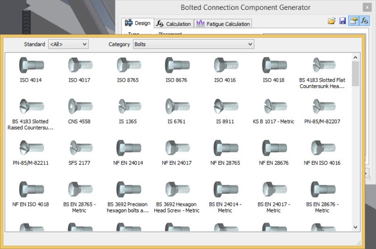
Hence, we have all basic requirements for create new Building ( Project ) in Revit because of what we have as a predefined Project Template and Default Family Content (Library).

I think now you know why we are going for Family in Inventor at first, let’s go for Part Modelling with IPT file and at same time we will try to make compare between this item and “Metric Generic Family” in Revit. Just follow below step for create first part (Family) in Inventor.

Or you can go for new part according to below picture :
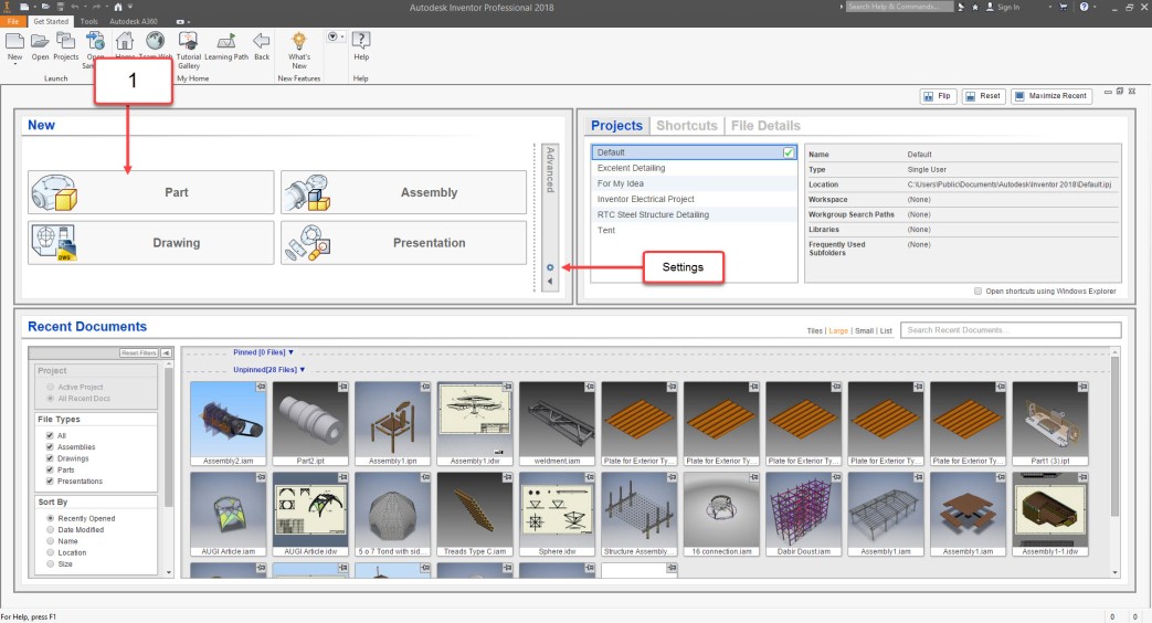
Note : If you have need to make change for default Template according to different Unit like Imperial to Metric or vise versa, you can go for setting like above picture and change the Unit and Standard as you can see in below.


Now you should have result like below picture, yes we are in Part ( Family ) environment.

At the same time you can go for create new family in Revit, as i said before that Family could be “Metric Generic Family” which is None Host Family.

As you can see in above picture we have many similar item in User Interface. Ribbon, Graphic Window, Project Browser/ Properties Panel=Design Tree.

Note: In Inventor if you need to go to the Isometric view ( 3D View in Revit ) just press F6 from your keyboard and if you need to make orbit, you can go for Shift+Click and drag with Scroll like in Revit. Also if you need to make zoom in or zoom out go for F3+Click and Drag with Left mouse button. You can use F5 for go to the previous view.

Now, i have one question, did you ever think why when you are working in Project Environment you have North, South, East and West view but when you are making model for Family, you have Front/Back and Left/Right view?

Answer is, Because you are making Product, yes Product and Inventor is very powerful for this part.

Ok, lets see what we have as Work Plane in Inventor?!!? Maybe you want to say what is the Work Plane? Work Plane is same like Reference Plane in Revit.

Like Revit in Inventor you have Default Reference Plane ( In Inventor you can call that Origin Work plane ) that is coming from the Family (Part) Template, Like Front/Back , Left/Right and Reference Level in Revit we have XZ, YZ and XY Work Plane in Inventor.  You can see how we can make compare between this item in below picture.


Ok, until now you know about Reference Plane, but one thing is remained here and that one is Family Type Dialogue in Revit !?! do we have anything like this in Inventor. Haha , yes, we have. Take a look to below pictures:


Please don’t forgot about this, Inventor is Mechanical Software and because of this we have more ability than Revit, in the future session we will discuss about many things for creating Parameter in Inventor but for now i can tell you one simple thing and that is about the name of parameter.

If you have parameter in Revit Like ” Frame Length” in Inventor you should type that as this way “Frame_Length” that mean is you can’t use space between words in Inventor and you can use “_” .


Good Luck

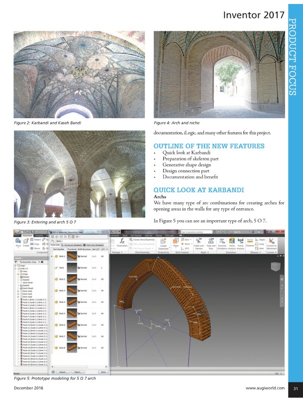
Second Article about Inventor Pro: Modern Design from Historical Perspective

Hi to all of my friends,

Many days are passed from the last post in my blog, now my new Article in AUGI magazine published in December issue.

I Should Say Thank you John Evans and David Harrington for your help.

You can download it from the below address:

https://www.augi.com/augiworld


Behzad Meskini


copy-of-2016-12-06_18-37-172

My first Article in AUGI Magazine

Hi,

This is my first Article in AUGI magazine, title is : Revit “WFRC” Method .

I must say thank Jay Zallan and David Harrington for reliability and giving me this opportunity.

This is my first experience and I should say sorry for my language but my hope is you take the base Idea from This article and use that in your projects.

You can download AUGI November issue from here: https://www.augi.com/augiworld/year/2016

Good Luck.

Behzad Meskini.

project-sample-1

project-sample-2

project-sample-3