I know this is not unique post but i’m sure this could be one of the useful post for all Revit or AutoCAD users,
I think that was around 12 years ago, i bought one book and i read one interesting thing about how we can understand what is happening in AutoCAD.pat file and how we can make decode that.
For that year, regarding to my experience and knowledge and also regarding to the explanation of that book , that was very hard for me to understand what is happening in *.pat file, but that was first start.
With many try i understood more about *.pat file, but every time i didn’t try for create more than 1 or 2 years i forgot something.
Now i want to make it documentary and share this with you my friend, then every time i forgot something i can make review this post for myself.
Let’s start this.
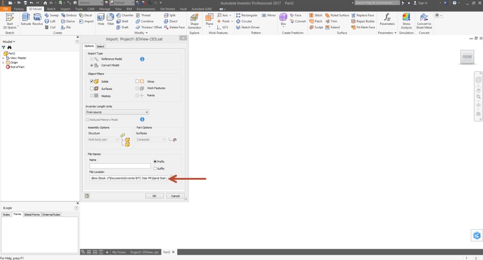
As you maybe know we can try to create *.pat file with notepad in our computer and after we wrote our codes we can save our files with .pat extension.
I want to explain this with three different type of Hatch with three separate post in my blog, all dimensions are mm.
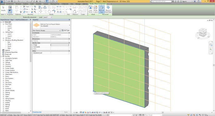
- Tile 300×300 Grout 10
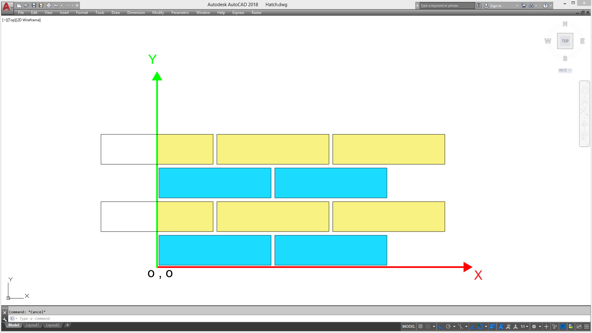
 Brick
Brick
2. Tile 300×300 Grout 10 Round Corner

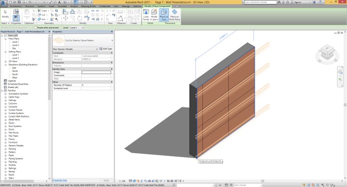
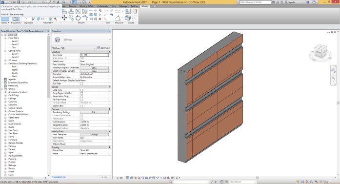
3. Brick 300×80 Grout 10

Ok, let’s talk about first item ( Tile 300×300 Grout 10 )
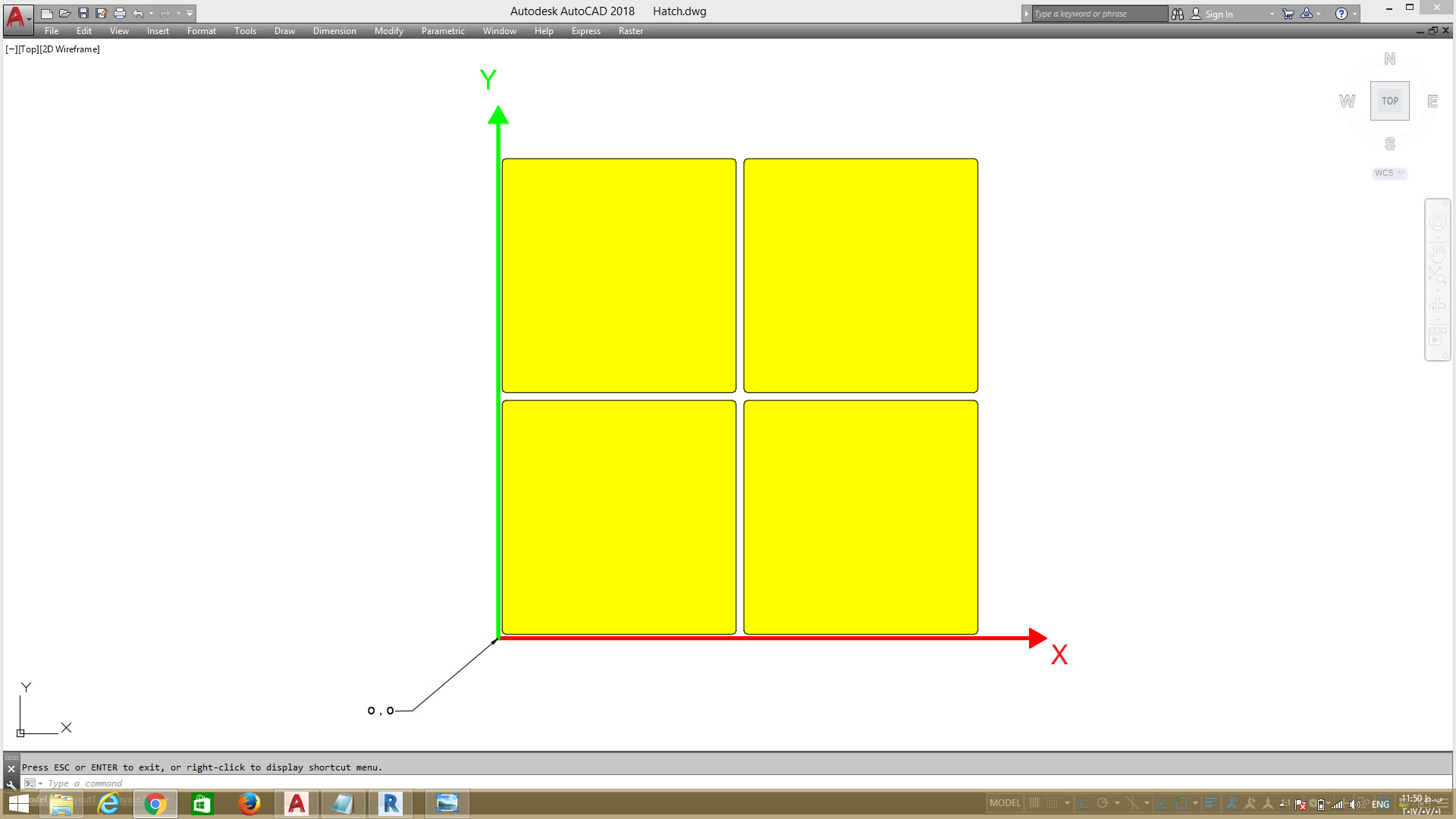
At first i should tell you one important point, if you need to define any new hatch, my offer is try to draw that hatch with line in AutoCAD regarding to simple X,Y axis like to the below picture.
Honestly, this is very important for you if this is first time you are making *.pat file and if you are making complex hatch pattern.
Because you can understand what is happening in pattern, for example for each pattern you need to have information about separate item like below list:
- what is the base shapes for pattern?
- How many line you need to create that base shapes shape?
- What is the Angle for Lines? ( We call that Angle )
- What is the start Point coordinates for each Line regarding to 0,0? ( We call that A for X and B for Y )
- What is side offset for each lines? ( We call that C )
- what is the exact side distance between line pattern? ( We call that D )
- what is the length of that lines? ( We call that E )
- what is the Gap between lines? ( We call that F )
In next steps i will answer to above question one by one. But before we start that i want to show you final result ( *.pat file ) for this simple hatch. take a look to below pictures. as you can see


1. what is the base shapes for pattern?
Take a look to below picture, as you can see we have one simple square ( Main Tile ) and we should make pattern from this shape along to X and Y axis.

As you can see in below picture Tile (Square) size is 300mm and Distance between Tile is 10mm.

2. How many line you need to create that base shapes shape?
As we said we have Tile with 300mmx300mm and for create any square we need four line. Take a look to the below picture, you can see four line and as you can see, this lines have sort of pattern .

3. What is the Angle for Lines?
Line 1 and 3 are parallel with X axis, that means is the angle value for this line is 0.
Line 2 and 4 are parallel with X axis, that means is the angle value for this line is 90.
4. What is the start Point coordinates for each Line regarding to 0,0?

line 1

Line 2

Line 3

Line 4

5. What is side offset for each lines?
Ok, take a look to the below picture, as you can see we have line 1 along to X direction and we said, angle for this line is 0. But if you pay attention we should have have parallel pattern from Line 1 for Tiles, that are duplicating along Y Direction. Number of this pattern is unlimited.

Now take a look to below picture, as you can see if you need to move Parallel pattern of Line 1 along to X direction you can add value for ( C ). This number is side offset for Line 1.

6. what is the exact side distance between line pattern? ( We call that D )
Take a look to below picture, as you can see we have distance between Parallel pattern of Line 1. you can see same thing for other lines.

Line 2

Line 3

Line 4

7. what is the length of that lines? ( We call that E )
Take a look to below picture, as you can see, length for all lines is equal with 300.

8. what is the Gap between lines? ( We call that F )
Final item is Gap between co-linear lines. Take a look to below picture, you can see we have Gap between Line 1 Co-Linear pattern and that one is equal to 10.
The only point is, we should use minus number. then -10.

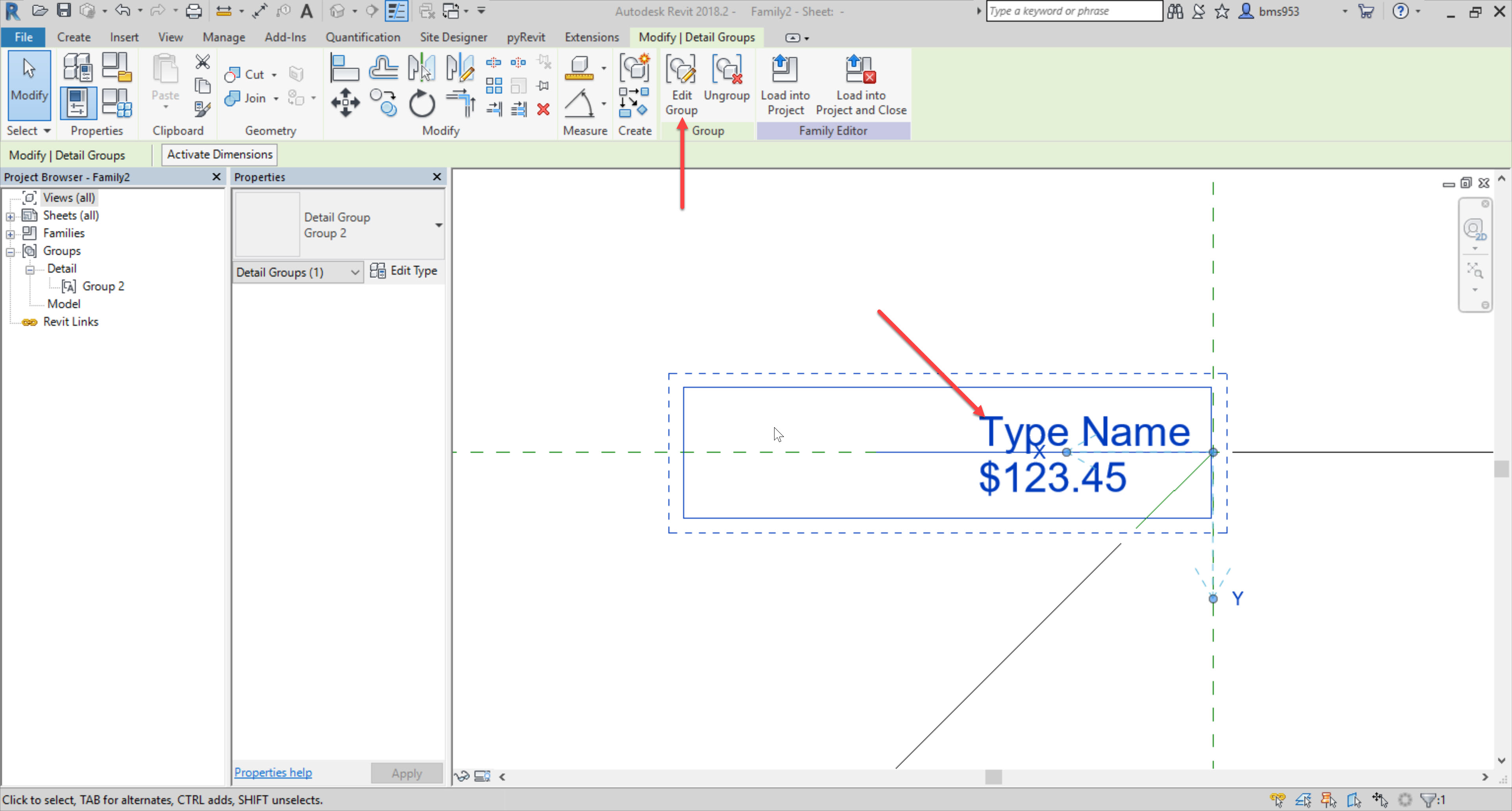
Now we have final result as new pattern for our usage in Revit.
Good Luck.


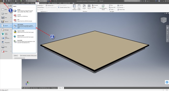


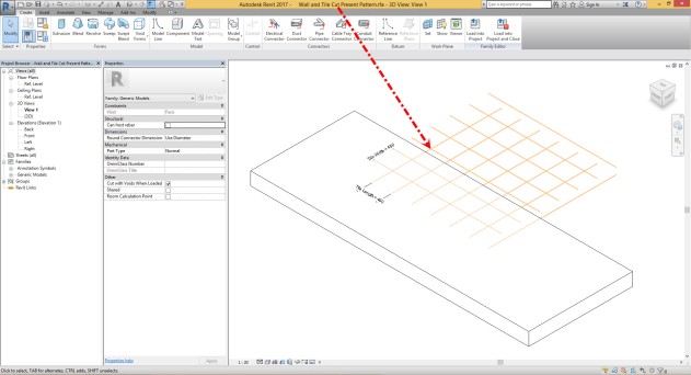


 You can download Revit Project file from here