Addressing issue for Level and Grid Bubble size in different view scale?!

Hope you all are doing well!

Let’s address another issue that we usually face in our projects,

Most probably you have faced this issue before, imagine you are in the elevation or plan view and you need to change your view scale from 1:100 to something like 1:200 or 1:50, your grids and level symbols will not be presented with the proper size. They are either interfering with each other or quite small.

There are some workarounds, like design options or using separate link files for different scales. And I would say each of those workarounds will cause other issues, such as productivity and flexibility.

In the following video I will demonstrate how you can address such cases in your projects,

Hope you like it,

Behzad

Control Room Separation Lines across different Disciplines

Hi again,

Tonight i want to share another tricks which i shared in BiLT ANZ 2018,

Let’s solve one of the big issue and answer to this question, How we can control Room separation lines in Link file, when we are sharing model across different disciplines?

This is one of the biggest request from M&E people, when they are creating space in M&E file they need to define their spaces with freedom and without any restriction from Archi layout.

You can see one example in below.  in left side we have Room separation lines, which you can see with red color.


Regarding to Archi discipline for this building we have separate area for manager, reception, counter and lobby. And the way they are defining this separation is according to furniture placement, different material or partition system.

But maybe for M&E, all of this area are part of one space and no need to define separate space for each portion.

Now if we go for M&E file and make try to define Space in according to Archi Layout, this will not be possible.


Go to Archi Model and make try to define new Phase, you can call that “Room Separation Line”


Select all Room Separation line from model and after that for demolition phase, define Room Separation Line.

Yes just this, make save your file and go to M&E file, make delete all Space that you have for Manager, lobby, etc.  You should do it with Space schedule and select those space that you want to delete and make them delete from schedule.


Now if you retry it again still you can see same effect and you cannot make one space for all area.

Select your archi model link and go to Edit Type from properties panel. In Edit Type dialogue box go for Phase Mapping and change phase mapping system like below picture.

Everything is set up now and you can define new Space without any limitation from archi room separation line.


I hope you enjoy and this could help you for managing your project,

I received comment, trick was very simple, perhaps it is. 🙂

Revit is much simple than we think and in most of the time we can solve issues without Dynamo and scripting,

Take care,

Behzad

How we can define 2D Tags/Symbols with Rotate option?!?

Hi to all,

Now after while i just want to share one tricks with you, which i shared in BILTANZ 2018,

This is very useful tricks and i’m sure when you are delivering projects, you will face with this issue or you already face with it.

Just take a look to below picture, did you saw this before? one Tag with two label text, for example : Type Name, Column Location.


But, but because you need to present this label text with different direction you have to make duplicate from that and you have to define extra parameter for visibility to say for 45 degree which item should be presented, or for vertical and Horizontal.

let’s finish this story one time at all.

Just define one new Generic Annotation, you can say this should be Furniture Tag or any other Tag.


Define Label Text as you need and define right location regarding to reference point of two reference plane.

Go for another Generic Annotation Family, you can call that “For Angle Definition”. Define one annotation line like below picture,

Now just load it into your Furniture Tag Family and define location for placement like below picture.

Select Generic Annotation Family “For Angle Definition” and label text object and put them in the group.


Define one Reference Line with 45 degree like below picture and make it Pin.

Now you need to define one Angular Dimension between Reference Line and that annotation line from “For Angle Definition” family.

Call that “Overall Angle” and define another parameter “Angle”. In formula row for Overall Angle define this ” Angle+135 “.

Select angular dimension and make it change to Overall Angle.

As you can see in below picture, suddenly you will get sort of result like reverse for you text element.


Go for edit group and make edit your group according to below pictures and step that you can see.


Make click and drag on the grip that you can see and do this clock wise .


You will get result like below picture and say Finish Edit mode for group.


Move you group from reference location like below pictures to the center of family, which is intersection of two reference plane.


Like below.


Now go to family “For Angle Definition”  select annotation line and say turn off visibility. Load it into your Tag family.


Orwrite Existing Family .

Now you can define new family type regarding to any angle as you want. Like H,V,30,45,60 or any other.


Next trick will be next week.

Enjoy,

Behzad


Big secret in AU Session ; How we can create Tag with Rotate Parameter?

Every time i’m talking about tricks i’m receiving many feedback and in many case my friends around the globe, they are saying we are following precise workflow for doing this and we never though that could be easy as this way.

Always, at that momement i am very happy, because i think i’m teaching and also learning from their workflow.

One of the big tricks i want to explain in my AU Session for this year is about Tag with Rotate Parameter . That mean is you don’t need to have separate family for horizontal or 45 degree and also you don’t need to have one family with many Label Text in different angle.

Take a look to below pictures,


yes, it’s possible and this is the way we can push the limits.

I will share with you about this tricks in the future but for now i need your help.

Currently i sent proposal for AU University 2017 and i need your vote. If this type of tricks are interesting for you please go to the below website and make search for this two title:

  1. Revit : Golden Tricks for save your life!
  2. Re Invent Revit: Inventor for Revit Users!


http://au.autodesk.com/speaker-resource-center/call-for-proposals/voting


Good Luck.

Re Invent Revit: Session 4, 2D Sketch assignment

I think without assignment we will not achieve to anything, hence I thought maybe i should prepare some record from 2d Sketch environment. In some part of this records I will show you how we can do something in Revit and how we should do that in Inventor.
You can watch records in below, also i should say in next few days i will make more record about 2d Sketch.


After you tried for this, if you need any help just ask I will tell you how you can make fix problems.
Good luck.

AU Proposal for 2017 : “Revit : Golden Tricks for save your life!”

Dear All,

This is my second proposal for AU Vegas 2018. Again i want share with you my knowledge. I don’t know how much you had suffer for managing Room Separation line in M&E side but, One of the hottest trick for this session is about how you can make turn Off/On for Room Separation line in M&E side. Yes in Revit. Also about Room and design option and many other tricks for you.

Take a look to the description from below link, you can make search with “Golden Tricks” (I know my English it’s not prefect) and do vote for idea if you think i deserve for this.

http://au.autodesk.com/speaker-resource-center/call-for-proposals/voting

you can find more info about me from below links:

https://www.linkedin.com/in/behzadmeskini/

https://dddmodeling.wordpress.com/about/


Best Regards,

Behzad Meskini

AU Proposal for 2017 : “Re Invent Revit”

Dear All,

After many years work with Autodesk software’s and share my knowledge with other people in different community and learn from community know i want share my idea with you through the AU University 2018 in Vegas.

I wrote three proposal and this on is about Inventor and Revit, anybody is currently Revit user i really believe he/she could be next Inventor user just with simple mindset from Revit and 3d Modeling, you will become next generation of Inventor users.

Please take a look to au.autodesk web site from below link and read my class description, if you like that then vote for that in AU website.

http://au.autodesk.com/speaker-resource-center/call-for-proposals/voting

If you need more info about me just check my Linkedin Account or you find more info in my blog.

https://www.linkedin.com/in/behzadmeskini/

https://dddmodeling.wordpress.com/about/


I need you vote, please support me.


Best Regards,

Behzad Meskini

Re Invent Revit: Session 3, 2D Sketch

Now you know about many thing in Inventor, we can go for first modeling feature.

Like Revit or any other software, when you want to make extrude at first you need to have one 2d Sketch and after that you can go for Extrude command.

As you can see we have separate icon for create 2D Sketch.

But we have two major difference here:


  1. In Revit you don’t have separate command for create 2d Sketch and each time you are hitting Extrude command you will go to the Sketch environment and you can have access to 2d Tools like line, circle, rectangle and etc. But in Inventor you should have 2D Sketch at first and then you can go for Extrude. Take a look to the above pictures.

2. Another thing is about the Work Plane , in Revit if you are in Reference Level, Current Work Plane is Reference Level and if you are in Front/Back or Left/Right view you can use Set Work Plane command to make set one Reference Plane for 2D Sketch, but in Inventor after or before you run 2D Sketch tool you should select one Origin or User Work Plane or like in Revit You can select One Flat Surface for create new 2D Sketch.

In Inventor you have many tools for create 2d Sketch and honestly in some case you can’t find any equivalent tools in Revit but still you can find many similar tools and workflow, I can give you short brief about this tools in Inventor and you can read about that in below.

Note : In Revit we hadn’t any 2D Constrain until to Revit 2017, in this version you can see only new item and that one is about Tangent Constrain for Arc shape and you can see relevant picture in below:


Note : In Revit you can’t use Array Command for make Array from elements that we have in 2D Sketch.

Option Bar:  Before of short brief i should explain about Option Bar in Revit and equivalent item in Inventor, as you know after we run any tool in Revit we can find some option according to that tool in Option Bar i want to explain about this with two simple example :


1. Revit : Copy = Inventor : Copy  : As you can see in Revit you can run Copy command at first and after make select your objects, press Enter and then you will receive some option in Option Bar , but in Inventor after you run Copy command you can receive dialogue box regarding to the Copy and all option are appearing in dialogue box.


2. Revit : Offset = Inventor : Offset   ; As you can see for Offset Command After we run this tools in Revit we can see different option in Option Bar but in Inventor after we run Offset command we are not receiving any dialogue and with Right Click we can see some option like Loop Select or Constraint Offset and also if you make click at any objects you can define value for offset tool.

Note : In 2d Sketch environment we have 2d constrain which could be little strange for anyone who hasn’t any experience with this. But if you are that type of user in AutoCAD who is using Constraint then you can find many similarly way for apply 2d constrain.

In Inventor you can see after you run move command you will see Move dialogue box and then you can select your objects with selection button and define two point with location.

Note : All tools for draw are very similar to Revit.

Note : All tools for Modify are very similar to Revit


2d Rectangular pattern in Inventor : In Revit you can make duplicate 3d elements with Array Linear, the biggest problem is you can define one axis for this but here in Inventor you can define two axis for make array from 2d elements and actually this tools is very similar like AutoCAD Rectangular Array.

2d Circular pattern in Inventor : In Inventor we can make pattern from 2D Elements with Circular Pattern and the only thing you need to define here is about the object for duplicate and Center of array, also this tool is like AutoCAD.


Inventor Mirror : Take a look to above picture

Note : In Industrial Software like Inventor we have different color for 2d Sketch elements and also if we have any sketch with all dimension that we need to make control for size and location of sketch, we can call that Fully Constrain. I will show you one simple example in below pictures and in the future we will learn more about this:


You can see one Rectangle with all dimension as full constrain and another Rectangle without dimension as a free shape. pay attention to the color.

As we said we will discuss about this in the future.

Good luck.

Re Invent Revit : Session 2

Ok, Second Session is about modelling procedure, after short explanation in “Session 1″for file type in Inventor and compare that items with Revit now it’s the right time for start new model in Inventor.

But before we start to talk about this item, i should tell you one things about what we are doing usually in Revit and what we should do in Inventor.

Every time i’m teaching Revit, i’m explaining about Project Environment at first then after that i’m going for Family.

The point is in Revit because of two thing:

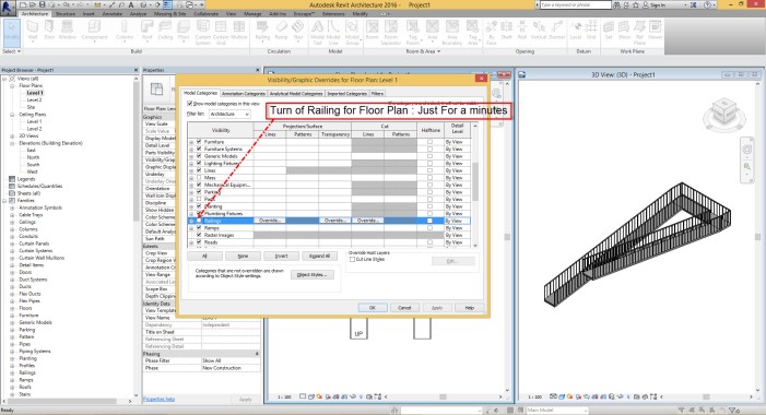
  1. Template for create new projects. (In every project template, we have different type of Wall, Floor, Roof, Ceiling, Stairs, Railing, as system families and also we have different type of Loadable family like Furniture, Columns, Beam, Door, Windows)
  2. Default Content Library. (We can find many different type of Furniture and Column, Door, Window, Tag, … etc that are very useful for start new project)

we can start from project.

Just for one moment imagine this in Revit, you starting new project, but you don’t have any family?!? I’m talking about all family like Systemperature Family, Loadable Family or Model-In Place Family.
Now what you should do?!?! Yes, you should create all things by your own.

—————————————————————————————————————————————————————————————–


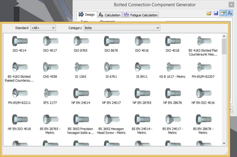
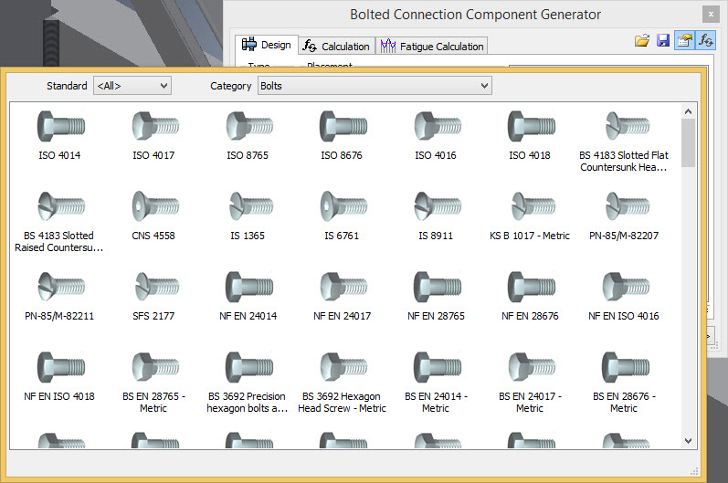
Note: If we try to make compare as this way it’s not fair , because I can say in Inventor we have biggest default content in the world for industrial usage. Pay attention, Industrial. It’s not Door or Window it’s Screw, Nuts, Washers, Pin, Ball bearing, Roll Bearing, O Rings and etc. If i remember correctly more than 650,000 parts.

——————————————————————————————————————————————————————————————–

Hence, we have all basic requirements for create new Building ( Project ) in Revit because of what we have as a predefined Project Template and Default Family Content (Library).

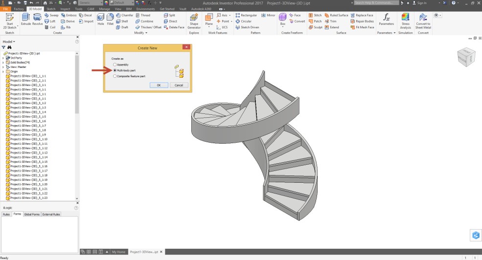
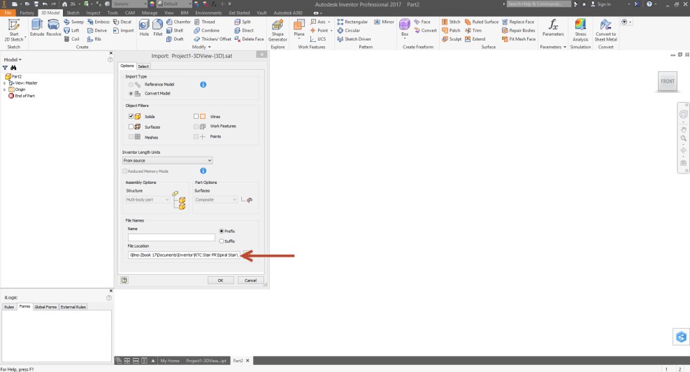
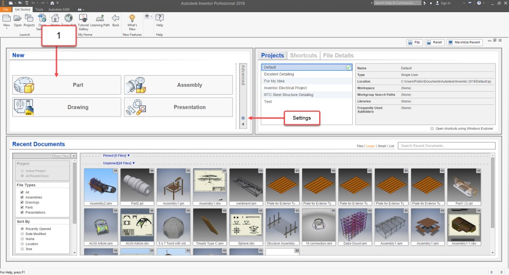
I think now you know why we are going for Family in Inventor at first, let’s go for Part Modelling with IPT file and at same time we will try to make compare between this item and “Metric Generic Family” in Revit. Just follow below step for create first part (Family) in Inventor.

Or you can go for new part according to below picture :

Note : If you have need to make change for default Template according to different Unit like Imperial to Metric or vise versa, you can go for setting like above picture and change the Unit and Standard as you can see in below.


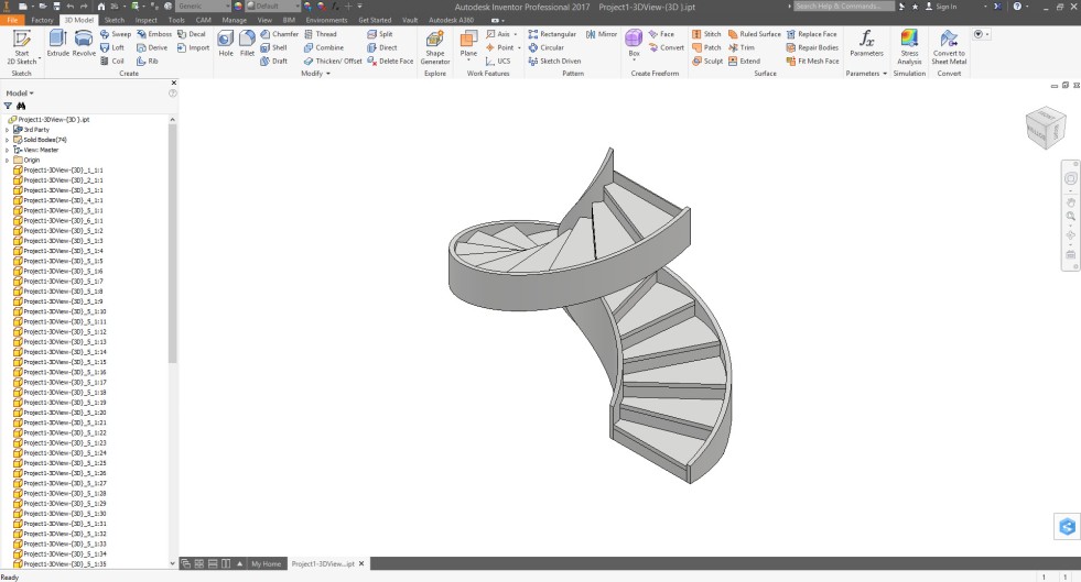
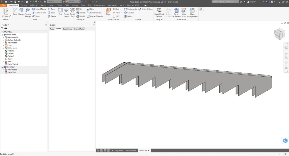
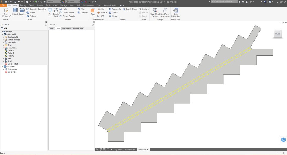
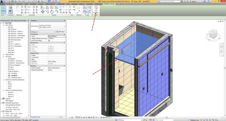
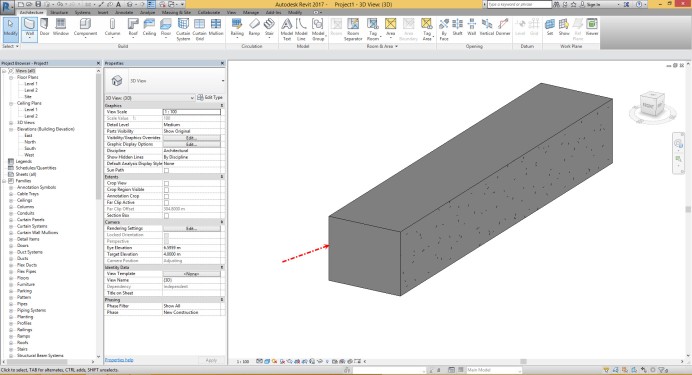
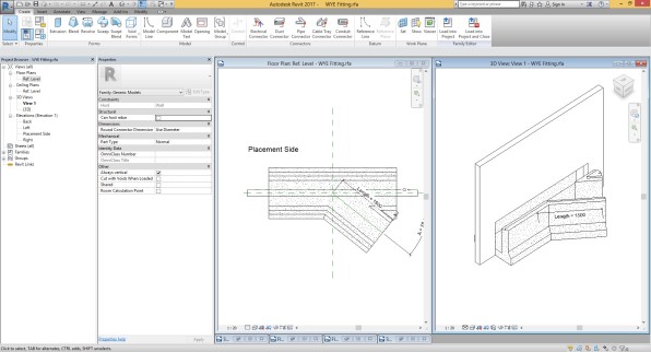
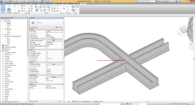
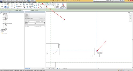
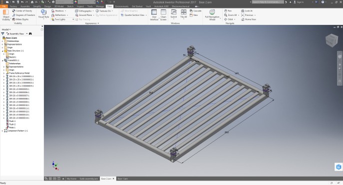
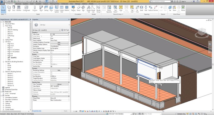
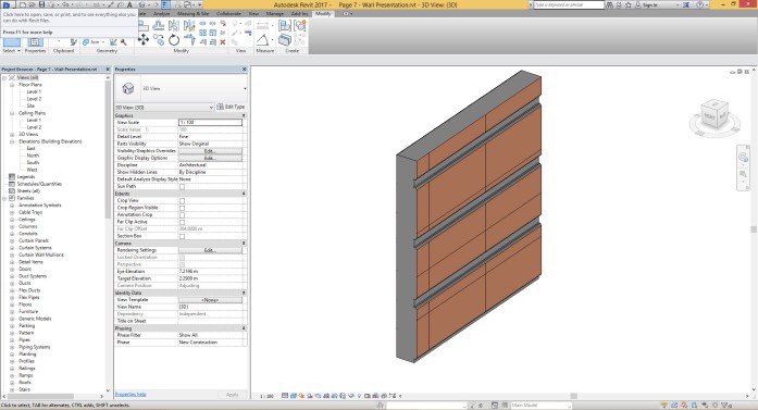
Now you should have result like below picture, yes we are in Part ( Family ) environment.

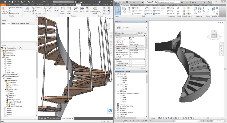
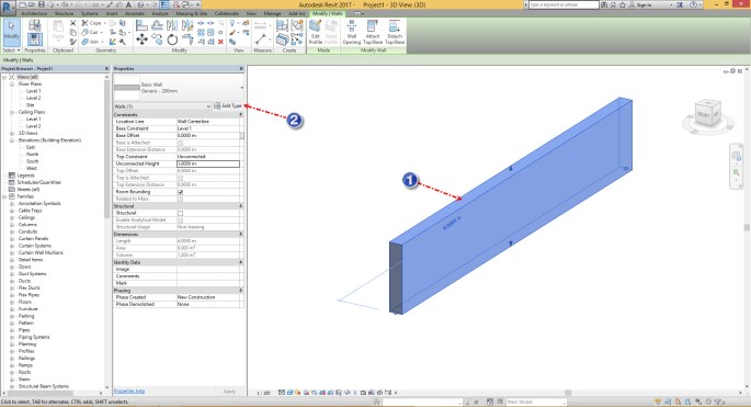
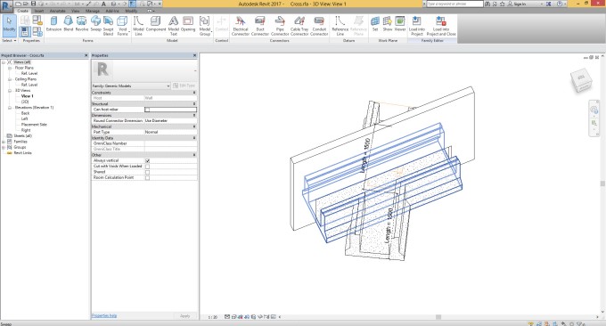
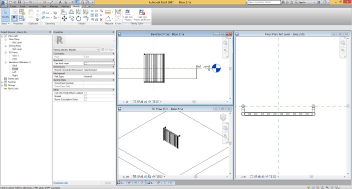
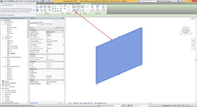
At the same time you can go for create new family in Revit, as i said before that Family could be “Metric Generic Family” which is None Host Family.

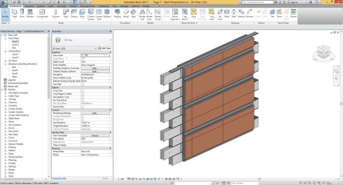
As you can see in above picture we have many similar item in User Interface. Ribbon, Graphic Window, Project Browser/ Properties Panel=Design Tree.

Note: In Inventor if you need to go to the Isometric view ( 3D View in Revit ) just press F6 from your keyboard and if you need to make orbit, you can go for Shift+Click and drag with Scroll like in Revit. Also if you need to make zoom in or zoom out go for F3+Click and Drag with Left mouse button. You can use F5 for go to the previous view.

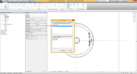
Now, i have one question, did you ever think why when you are working in Project Environment you have North, South, East and West view but when you are making model for Family, you have Front/Back and Left/Right view?

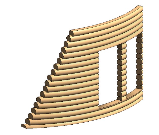
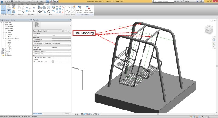
Answer is, Because you are making Product, yes Product and Inventor is very powerful for this part.

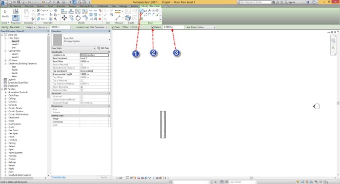
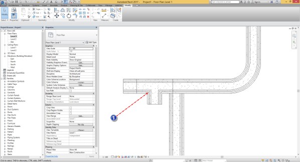
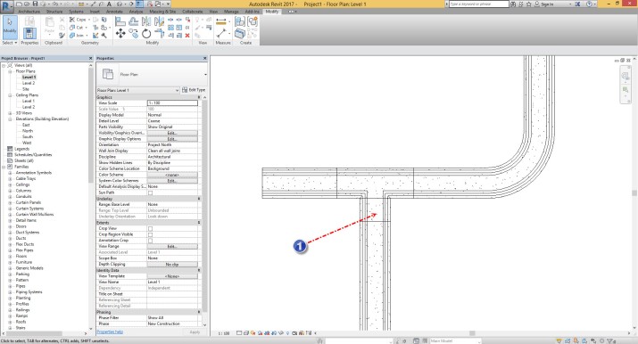
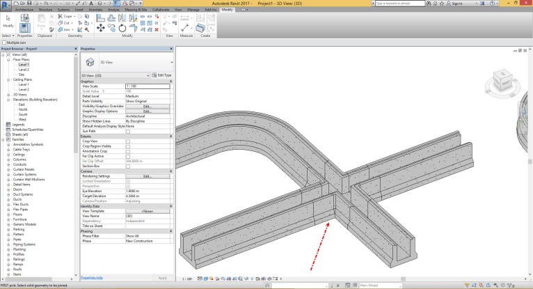
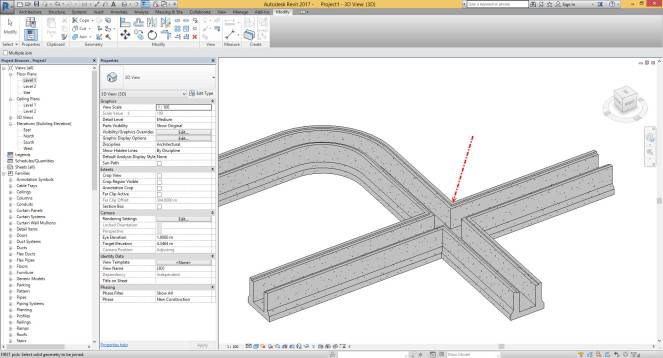
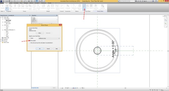
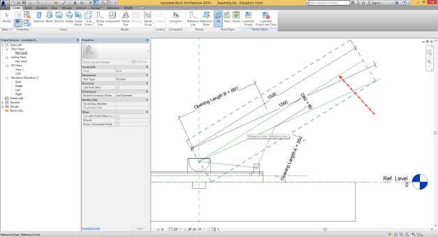
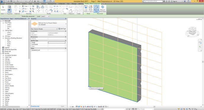
Ok, lets see what we have as Work Plane in Inventor?!!? Maybe you want to say what is the Work Plane? Work Plane is same like Reference Plane in Revit.

Like Revit in Inventor you have Default Reference Plane ( In Inventor you can call that Origin Work plane ) that is coming from the Family (Part) Template, Like Front/Back , Left/Right and Reference Level in Revit we have XZ, YZ and XY Work Plane in Inventor.  You can see how we can make compare between this item in below picture.


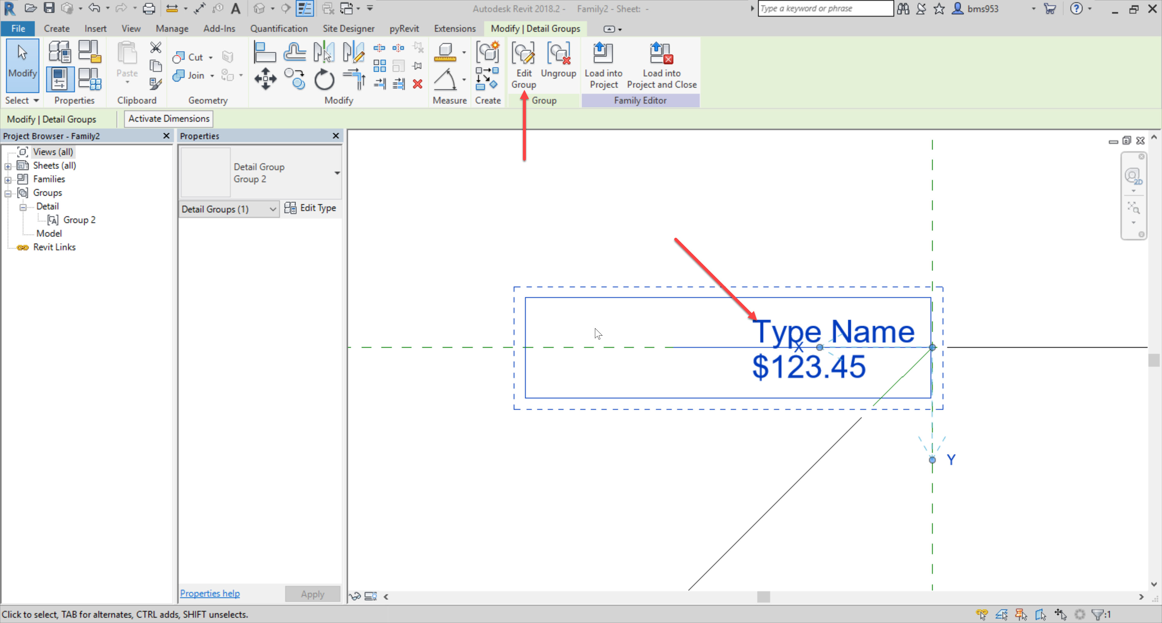
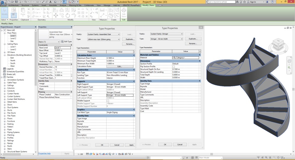
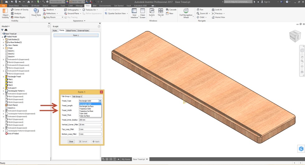
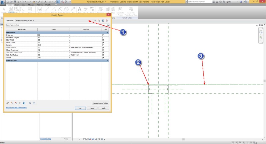
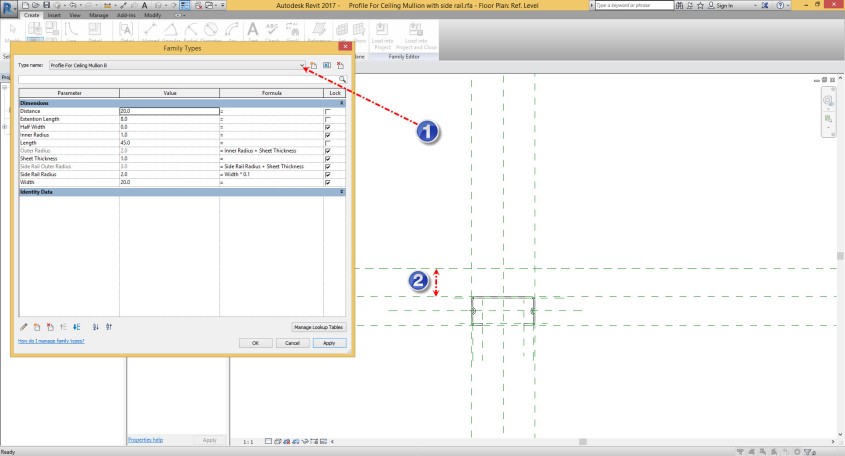
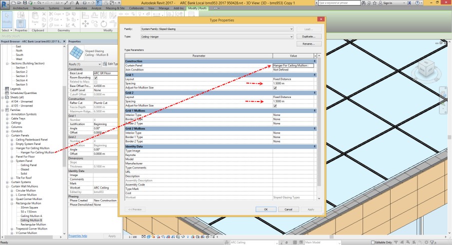
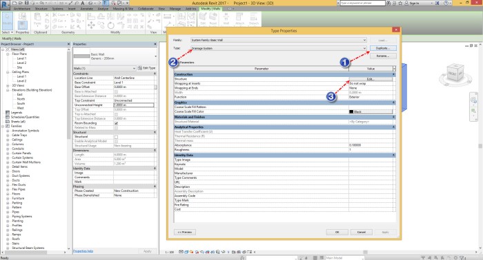
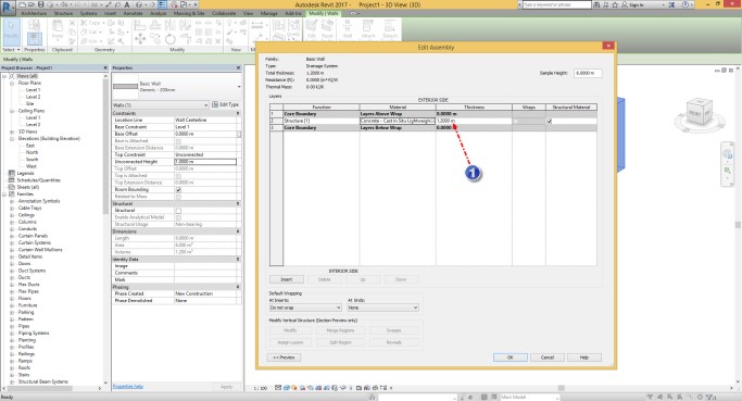
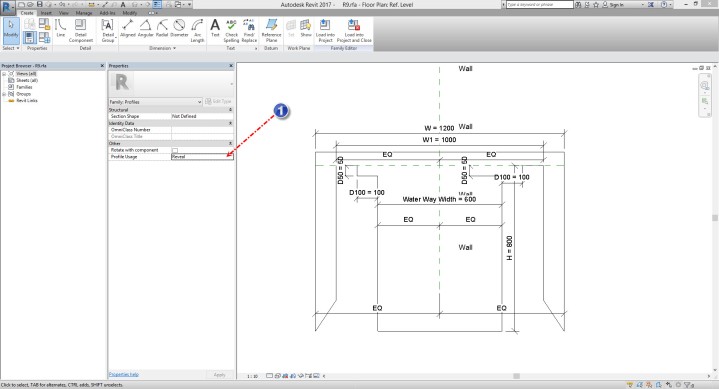
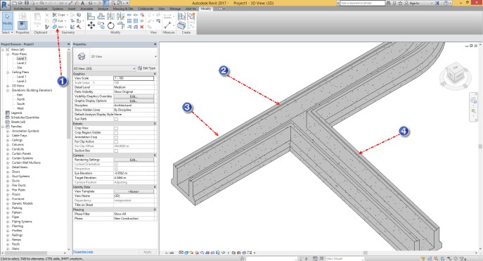
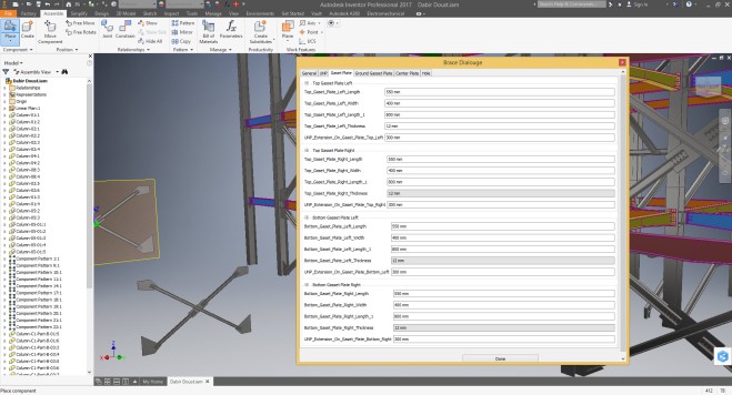
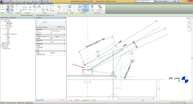
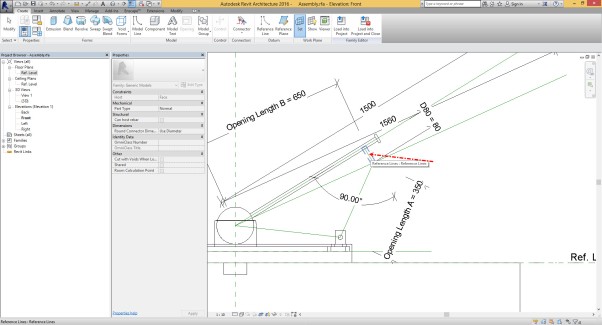
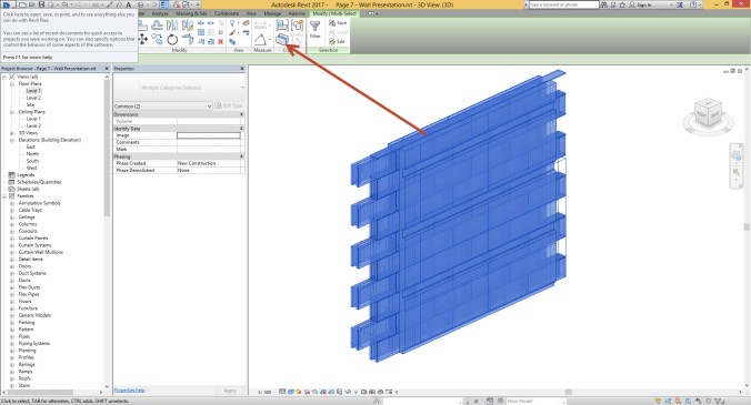
Ok, until now you know about Reference Plane, but one thing is remained here and that one is Family Type Dialogue in Revit !?! do we have anything like this in Inventor. Haha , yes, we have. Take a look to below pictures:


Please don’t forgot about this, Inventor is Mechanical Software and because of this we have more ability than Revit, in the future session we will discuss about many things for creating Parameter in Inventor but for now i can tell you one simple thing and that is about the name of parameter.

If you have parameter in Revit Like ” Frame Length” in Inventor you should type that as this way “Frame_Length” that mean is you can’t use space between words in Inventor and you can use “_” .


Good Luck

Re Invent Revit : Session 1

First Session is about how we can start to work with Inventor. Remember, my mindset is, currently you are working with Revit, then you know about 3d Modelling and you know about Project and Family well.

but be aware about this in Inventor we have different way for modelling and different solution for do anything, hence when i’m explaining anything that item could be about usual items and maybe we could find many different way for do same things, another things is, every time i;m trying to find any method or item to make compare with Revit and say about same solution with Inventor

OK, every time i had any class for anybody or any groups they have one similar question, when we opened Inventor software at the first time we saw one dialogue box and we was confused what we should do and which item is correct for our work.

Take a look to below Picture, yes this is what they saw in first try with Inventor.


Let me explain about first dialogue according to Revit perception.

Description : As you know every time you want to make any project in Revit you need to put some family together, Like Wall, Floor, Roof, Ceiling (System Families) Window, Door, Furniture, Mechanical Equipment, Case work (Loadable Family=User Family ) Mass , Generic Modelling in Project (Model in-Place ) . Hence any project is combination of Family.

Here in Inventor Part is equal to Family and Assemble is equal to Project.

Simple clarification :

1. Revit : You can make a Project in Revit and bring other projects as a link into that = Inventor : In Inventor is same you can make an Assembly and bring other assembly as a Subassembly the only different is in Inventor you can make edit in any subassembly as you want but in Revit you cant make edit in Link object.

2. Revit : You can Make a Family in Revit and load it into other family as a nested family ( With this Method you are trying to make Sort of assembly in Revit )= Inventor : Usually in Inventor when you want to make assembly you can put Part object in Assembly file, (( I should say still you can make a Part and load that Part in new Part as a Drive Part) ( Also you can load Assembly in Part ))

3. Revit : In Revit you need to do modelling for Projects, in Project Environment = Inventor : In Inventor you need to make your Parts and put them together to make your Assembly ( Project ) .

Note: Actually you can do modelling in Assembly Environment with two different way and you can read about that in below .

5. Revit : In Revit Project Environment you can create Model in-Place Family and you have all feature according to Family Modelling in Project Environment = Inventor : In Inventor is same, you can use Assembly Feature and make join or cut with Part solid models, but you can not save this Feature as a new *.ipt Part and they are part of Assembly environment

6. Revit : In Revit Project Environment you can create Model in-Place Family and you have all feature according to Family Modelling in Project Environment = Inventor : In Assembly Environment you can create new Part and make active your Part Feature and create parts inside of Assembly , Difference is in Inventor you can save that part as separate Family but in Revit normally you can not do this.

Revit Family = Inventor Part

File Extension for Revit *.rfa = File Extension for Inventor Part *.ipt

Revit Project = Inventor Assembly

File Extension for Revit *.rvt = File Extension for Inventor *.iam

Simple clarification :

Q 1 ; What is the Sheet Metal.ipt ?

A 1 ; As you can see Sheet Metal.ipt is sort of Part in inventor but you can find different feature for modeling, all feature are relevant to Sheet Metal Objects, Like Water Tank, Metal Cabinet, Metal Desk, Metal Door, Cladding,

Q2 ; What is the Weldment.iam ?

A2 ; IN any case that you need to do Welding projects you can use Weldment.iam.

Q3 ; What is Standard.idw ?

A3 ; With Standard.idw file you can create drawing from any *.ipt or *.iam file , important point is in Revit you have Sheet Subset in Project Browser and Annotate Ribbon for Dimension and Symbol. But in Inventor you have separate file type (*.idw) and environment for prepare drawing.


Q4 ; What is Standard.ipn ?

A4 ; Naturally Inventor is a software for Mechanical Engineers and Product Designers, in many case this people needs to make a presentation from their Assembly, that how we should make assemble or disassemble any mechanism .  If we want to make example like this in Revit we should talk about Displacement tool. you can see similar result in Revit and Inventor in below picture.


We will discuss about modelling workflow and we will compare Revit solution with Inventor solution in the future.

Good luck.

Useful trick , Break schedules per sheet in Revit.

Ok, another trick.

As I know many of you are looking for workflow to separate schedule per sheet, and I wan to show you how you can do this.

For start you can open rac_basic_Sample_Project.rvt . Go to the sheet A001 – Title Sheet. You can find schedule here.

10-6-2016-3-28-01-pm

Select the schedule at this sheet and hit the symbol as you see in the below picture.

10-6-2016-3-28-15-pm

Now you have two separate schedule in the sheet. Also you can try to make some adjustments with the grip as you see in the below picture.

10-6-2016-3-32-20-pm

Next step is very important, because you need to make move with the little icon that you can find in the target of arrow 1.

You need to move the schedule with the distance over of the length of the sheet. Also you will be careful about the position between the parts of schedule table. I prefer to use otrack that you can see when you want align the top of the schedule table together.

10-6-2016-3-32-48-pm

You are able to create several separation between the schedule.

10-6-2016-3-35-46-pm

And make move according to that rules I said before.

10-6-2016-3-36-19-pm

Go to the next sheet and try to move all of the schedule together and put that schedule you want appear in the sheet area.

Just with simple click and drag on the schedule.

( you should not to use Move symbol in the left of top corner )

10-6-2016-3-38-09-pm

As you see in the below picture the position between of each parts not changed , just move all of table together.

10-6-2016-3-38-30-pm

Put the last table in the next Sheet.

10-6-2016-3-39-50-pm

For the final step you need to some adjustments in print dialogue like the below pictures. Go to the print dialogue and turn on which sheets as you need.

10-6-2016-3-40-58-pm

Go to the setup for printer and select the right Sheet size , change the paper placement like the below picture, and change the zoom to the zoom 100 % and hit the OK button .

*** Note: To be able to get right output in second, third or etc, you need to use user defined offset and specify specific length between your schedule and boundary of your sheet. (Revised on 2019/03/12)

You can see the result and every thing is ok, I hope you enjoy this.

10-6-2016-3-44-17-pm


RTC Events Singapore 2017, 2nd Abstract Steel Structure Detailing with Autodesk Inventor and iLogic Parts

This is my honor to be a part of RTC Event 2017 in Marina Bay Singapore as a speaker.

In my opinion Inventor is one of the best software for customization around what you want as a fabrication modeling and documentation. Because of this and because of many other ability that we could find on this software, I used  this software for Steel detailing. Combination between regular modeling and iLogic ability gives us huge power for complex job like Shop drawings.

If you are interest to be attendance at this event I will say welcome to you and I hope to see you in RTC Event 2017, Singapore at 30 March – 1 April.

Also, thanking the RTC Committee , Richard Kuppusamy  , Heidi Lam and Phil Lazarus for what you are doing as a volunteer for RTC .

autodesk-inventor-1

Taking Stair from design to fabrication with Revit and Inventor, just in 10 minutes.

Many of my friend in the fabrication industry asking me about the workflow for making documents for stair fabrication.

I refer them for using Autodesk Inventor because of ability of this software.

At this post I want to show you how it could be simple for Revit and Inventor users to create an assembled stair with full of detail just in 10 ,

Let’s start,

What we need as a material is very simple, First step is design what you need with the precise overall dimension in Revit and this could be very easy in Revit. Like the below picture I create an stair with spiral shape between two level with 3.24 meter height.

Stair Width = 1 m

Stair tread Depth = 0.3 m

Maximum Riser Height = 0.18 m

Stair stringer Size = 0.05 m x 0.4 m

Structural Depth on Run = 0.15 m

Structural Depth on Landing = 0.3 m


10-1-2016-12-29-39-am

you can use Isolate command in the project area for which stair that you want create detail.

Go to File > Export > Cad Format > ACIS *.sat

Now Start Autodesk Inventor and open SAT file in Inventor as a Part with multi solid body

10-1-2016-12-40-04-am

Make sure about where you are saving the file.

10-1-2016-12-40-33-am

The result should be like the below picture. you can save it with ipt format.

10-1-2016-12-41-22-am

You can create regular helper object ( Work Axis and Work Points ) for the future modeling like the below picture.

10-1-2016-12-44-57-am

Create 3d Sketch like the below picture according to the Helper object ( Work Axis and Work Points )

10-1-2016-12-49-58-am

Create two Sweep as surface according to 3d Sketch and two simple 2d Sketch like the below picture. You will need this surfaces for manage the sweep command for that profile you want create with Generative shape design tool.

10-1-2016-12-53-20-am

Create a hole and make pattern from that hole with rectangular pattern like the below picture.

10-1-2016-12-58-13-am

Create an iLogic part with several option that you need as a tread for stair and use this for final stair.

10-1-2016-1-01-15-am

Create a new assembly and place that part you open as SAT format with multi body and saved with ipt format like part.

Now you are able to create structural frame for body of stair according to what you have in the basic model that you import from Revit and mange in the Part environment.

10-1-2016-1-05-58-am

Now you can place the first tread as iLogic part and the dimension for this tread is depend to the basic shape of stair in Revit.

10-1-2016-1-13-05-am

For the next step you can create pattern for this tread and use Feature pattern depend to the Hole pattern in the Basic stair part.

10-1-2016-1-15-26-am

Now go to the IDW environment and make some drawing.

10-1-2016-1-18-03-am

This is very fast and unique workflow for everyone who looking for fabrication in stair category.


9-29-2016-11-26-06-am

9-29-2016-11-29-24-am


10-1-2016-1-21-43-am

10-1-2016-1-21-57-am


Enjoy this.


How you can Create Timber Wall with precise Schedule and good presentation ?

At this post I want show you how you can create Timber Wall in Revit and I will follow two important things :

First is precise schedule Like volume of the wood or quantity of Timbers and Length for Timbers.

Second is Good presentation in the 2D and 3D View.

Page 10 B


perhaps you make some guess for this wall but if you want to go for do this with wall Sweep I can say you are going wrong because you can’t create schedule for which Wall sweep then coming from the edit structure Layer of the wall , another things is you should create thin layer in the Wall Layer dialogue box for create wall sweep in the height you want, this layer make your wall wrong.

Ok, Lets start

First thing is wall and you can create a Wall with thickness equal with the Timber Diameter For example  200mm

Timber 2

Then you need to Create 2 Profile for Reveal in the Edit Structure dialogue box.

Timber 3

You can see two circle for Timber separation in the below picture.

Timber 1

Now you can create some Reveal into the Wall structure like the below picture.

Timber 4

You can see what happened for your wall.

Timber 5

Try to place Door and Window in the Plan View.

Timber 6

You can see what happened in the 3D View.

Timber 7

Select the wall and go to the Edit Profile.

Timber 8

Like the below picture and hit the Finish button.

Timber 9

You can see the Result.

Timber 10

For the final part you can use Design option and make copy from the Walls without any door and window.

Timber 11

Then you can use Create Part command , you have good result and if you select any part in the project you can have access to what you need.

Timber 12

Interior View

Timber 13

Exterior View

Timber 14


Good Luck.

Big Secret, How we can manage height extension for Finishing Layer in the Walls?

This is one Biggest secret I want to tell you.

I have many Experience for Wall detailing and every time I want to manage the height Extension for wall I was in the biggest challenge .

The base method was unbelievable tough, you will go to the Edit Structure Dialogue and make unlock the top or bottom for finishing Layer and then change the Height for Top Extension and Bottom Extension Manually . I had many other limitation to , for example I cant change the height for interior and exterior layer individually and if I want to have the height extension with slop that wasn’t possible.

Now , you can see how much is easy to do this with this method .

As you see in the below picture we have an Toilet and many walls around the toilet and we have ceiling in the Toilet Area.

Ceiling A 1

Select all of the walls around the toilet and hit the Attach icon.

Ceiling A 2

Now you can see what happen for your wall. Pay attention I create the ceiling with extend to core option.

Ceiling A 3

Make some undo , select the Ceiling and select Edit Boundary .

Ceiling A 4

Create free Slope arrow and change the Height for tail and head to Zero.

Ceiling A 5

Select Finish Button and select the walls and hit Attach Icon.

Ceiling A 6

Now you can see what happen for your Wall finishing Layer. you can attach exterior layer and core boundary layer separately too.


Good Luck.


How We Can Create Stud Behind the Ceiling and Plaster board Panel of Ceiling in Revit ?

Hi I was a business trip in pas 3 days and now I came back , Lets start new trick

As I said before Sloped Glazing Roof is amazing tool in Revit , then for this trick we want use this command for Stud and panel in the Ceiling System.

I prepared all things you need for this method of Modeling :

  1. Profile for Stud ( Profile Type : Mullion ) with two Type .

you can see Type A in the below picture and as you can see this profile is connect with the base reference line of Profile Family.


Ceiling 17


you can see Type B in the below picture and as you can see in the ark ( 2 ) we have distance between Origin and bottom of Profile .

This distance is equal with the Width of the Stud Profile.


Ceiling 18


3.  Load the profile into the Project and use them for new Mullion Type as you can see in the Mark ( 1 , 4 ) and change the Profile family for each of them.

Ceiling 21


4. Another Part is Hanger for Stud. You can use Curtain Wall Panel for this.

Ceiling 19

5. Final Part is Plaster board panel and for this part you can make duplicate from solid panel and change the properties for panel like the below picture.

Ceiling 20

After preparation for this parts you need to make four new type in the Roof Sloped Glazing Type .

Type 1 ; Call that Mullion A and change the properties like below picture.

Ceiling 22

Type 2 : Call that Mullion B and change the properties like below picture.

Ceiling 23

Type 3 : Call that Hanger and change the properties like below picture.

Ceiling 24

Type 4 : Call that Hanger and change the properties like below picture.

Ceiling 25


After all preparation you can start with the procedure I will say in the next . I should say at this example I create base ceiling for project before I start to create stud.

Select the ceiling ( 1 ) and select Edit Boundary ( 2 )

Ceiling 1

Select all of the boundary line ( 1 ) and select Copy clipboard ( 2 )

Ceiling 2

Create new Roof by Footprint ( 1 ) and go to the Past drop down and select align to current view ( 2 )

Ceiling 3

Click on the Finish button , Select the Roof ( 1 ) change the height for placing the roof behind the ceiling ( 2 ) and select Copy clipboard ( 3 )

Ceiling 4

Hit the Align Same Place for 3 time to have 4 Roof in the same Place .


Ceiling 5


Select one of the Roof and change the type to Mullion A

Ceiling 6

Select another one and change the type to Mullion B

Ceiling 7

Select the third one and change the type to Panel 1.5×3 Meter

Ceiling 8

Select the Final one and change the type to Hanger

Ceiling 9

Select Delete Type

Ceiling 10

and then Select Replace Type.


Ceiling 11

Make your view as Isolated View . ( For selecting this panel I used Single Select method but for big boundary you can use Filter )

Ceiling 12

And change the type to Empty Panel .

Ceiling 13

Like Below Picture.

Ceiling 14


You will see your Stud System perfectly in the Project and other information like the shape of Panel and quantity of Panel.

Ceiling 16


Good Luck.


Quick trick, How you can create boundary for front view of wall when you have Sweep on that ?

Did you ever use Wall Sweep for your Wall in the Project modeling ? You can add many detail into the wall model but you have many limitation with this tool.

For example if you use Wall sweep in the edit structure dialogue then you are able to add many wall sweep simultaneously into the wall and all of them creating automatically , but the problem where coming you want to create schedule from this wall sweep , you are not able to  create schedule for this type of wall sweeps.

But if you use Wall Sweep Command every thing is different , you can create schedule for this but you can’t create many of them simultaneously in the project area.


Other problem for both of them is about the font view of wall , in the normal wall which has not any wall sweep you can use Edit Profile Command for change the boundary of the front view for your wall , but you can’t use Edit Profile Command for this type of Wall !!?! maybe you think you can do this , pay attention what is the result for the final model of wall?? could you cut your sweeps as you want ?? with the shape you want ??


In the Next I will explain how you can solve this problem.

Let’s start, I prefer to you create four wall and use Edit Profile command for them like the below picture as you see every thing is ok.

sweep 1

Then make a copy from them and change the type for this walls to another type which has wall sweep. You can see what happening when you have wall sweep into the wall . every thing is for cutting wall sweep are wrong.

Sweep 2

If you select a Wall for example like the below picture and go to the Edit Profile you can see the boundary line.

Sweep 5

And when you finish Edit profile command if you select the wall and pay attention to the Wall sweep point you can understand what happened . In fact the wall sweeps are finishing in the intersection point between the boundary line and guide line of wall sweeps.

Sweep 6

Go to the Edit structure dialogue and check the wall sweep and option for them like the below pictures.

Sweep 3


Sweep 4

Now we can fix this problem very simple. go to the Model in Place area

Sweep 7


You can choose Generic Model


Sweep 8

Run Opening Command ( 1 ) click on the ok button for choosing host of opening ( 2 ) and select which wall you want ( 3 )

Sweep 9

Create your own area s you want and then press Finish icon.

Sweep 10

Select Finish family too.

Sweep 11

you can watch what is the result for your wall, every thing is ok.

Sweep 12

You can do this as the same way for other walls.

Sweep 13


In fact you can add some parameter for which wall has wall sweep in the Edit dialogue of wall and get the correct result for scheduling sweep material.

Good Luck

How we can create drainage system in Revit ?!?

Ok, I saw many people , who are creating drainage system with model in place tool and in my opinion they are working too much for doing this.

Now I want show you how you can create drainage system more than simple then you can think.

All thing you need is a Wall and a Profile.

Let’s start.

Create New Wall ( 1 ) and go to the Edit Type ( 2 )

Drainage 1

Create Duplicate form the Type and Call that Drainage System

Drainage 2

Make change the Thickness for this wall.

Drainage 3

You will have wall like the below picture.

Drainage 4

Now you need to create a profile for Reveal like the below picture and change the usage to reveal , load this profile into the project area.

Download Family : http://s7.picofile.com/file/8259765142/R9.zip.html

Drainage 5

go to the Edit Type and add Reveal for Wall like the below picture.

Drainage 6

Now you have new Drainage wall in your project and good information then you can use for schedule and you can count your Walls in the project area.

Drainage 7

Go to the plan view and Run the Wall Command , turn on Radius option and change the value for Radius .

Drainage 8

Create your Wall .   What you feeling now ????

Drainage 9

But something is remaining , What happen if you create branch from the main line ?

Drainage 10

Go to the 3d View for recognizing the problem. How we can fix this?!?!

Drainage 11

Drainage system is very similar to Duct system, then we can create some Fitting part for this system and this family can fix the problem for us.

You need to create family like the below picture. the family should be wall based.

http://s6.picofile.com/file/8259765118/WYE_Fitting.zip.html

Drainage 12

Load the family into the project area and place the family in the floor plan view and change the branch angle in the Instance properties dialogue .

Drainage 13

Now you can use Align command for aligning between wall center line and the reference plan of the fitting.

Drainage 14

Go to the 3d View and use join command for joining the family and wall together.

Drainage 15

For cross section you have same problem .

Download family : http://s6.picofile.com/file/8259765100/Cross.zip.html

Drainage 16

And you can use same method .

Drainage 17


Drainage 18


Drainage 19

At the Final you have every thing you want , Fast modeling , Precise schedule , Fast Editing , etc.


Good Luck


Just Experience sharing , Steel Structure Detailing with Autodesk Inventor Professional !?!

I Said before my opinion About the Autodesk Inventor Professional.

Then three or four years ago is start to create my own plugin to build steel structure with Inventor Pro.

And I did some project with this plugin , Autodesk Inventor is very useful and very powerful for modeling.

aa


aaa


I Send This Proposal For AU Las Vegas , but ……

Good Luck.

Ball Constraint ,Slide Constraint , Cylindrical Constraint in Revit !

As I said before I want to show you how you can crate this type of constraint in Revit Like Inventor Professional.

Let Start ,

For this assembly we need six part as you can see in the below picture:

1.Rotter Part

Ball 1

Download Part : http://s6.picofile.com/file/8259515042/Rotter.zip.html

2. T Shape Slider Part

Ball 2

Download Part : http://s6.picofile.com/file/8259515050/T_Shape_Slider.zip.html

3. Ball Pin

Ball 4

Download Part : http://s6.picofile.com/file/8259514942/Ball_Pin.zip.html

4. Pipe Slider Part

Ball 6

Download Part : http://s7.picofile.com/file/8259515018/Pipe_Slider.zip.html

5. Piston Part

Ball 3

Download Part : http://s6.picofile.com/file/8259515026/Piston.zip.html

6. Cylinder Part

Ball 5

Download Part : http://s7.picofile.com/file/8259514992/Cylinder.zip.html

Now we can start our assembly. you need to create new Family and call that Assembly in my opinion Face Base family is prefect . from the Insert Ribbon run the Load Family Command and load all of the part into the assembly family.

Ball 7

  1. place the Rotter family with this option and pay attention to the Reference Line in the mark 2 and 3

Like the below picture you can go to the front view and create new Reference Plan and make align for this reference plan, then you can call that for example a.

Ball 8

Like the below picture create a reference line make align from the start point ( 3) between to reference plan (4 , 5 ) and create an angular dimension between reference line ( 1 ) and reference plan ( 2) create a parameter from this dimension and call that for example Rotor angle

Ball 12

Set the work plan of reference line like to below pictures

Ball 13


Ball 14

Place the T Slider shape component on like the below picture and set the correct position for this part.

Ball 15

Go to 3d View and change the Rotor Angle parameter for test.

Ball 16

Change the work plane to the another work plan of reference line then you draw before and go to the front view.

Ball 17

Ball 18

Ball 19

Run the reference line Command and start to create from the intersection below pictures.

Ball 20

Ball 21

Create three reference line like the below picture.

Ball 22

add some parameter for this reference line , the length for reference line ( 3 ) is fixed and two other parameter are instance.

Ball 23

Change the work plan like the below pictures.

Ball 24

Ball 25

Create new reference line ( 1 ) and add fixed dimension for this reference line , then you need to create dimension depend to the Pipe slider part ( 2 )

Ball 26

change the reference plan like the below pictures.

Ball 27

Ball 28

place the Ball pin part and change the position and orientation like the below picture.

Ball 29

create new reference line  ( 1 ) and then add angular dimension ( 3 ) and make align between the new reference line and the end of reference line ( Opening Length A )

Ball 30

Set the work plan like the below pictures.

Ball 31

Ball 32

Place the pipe slider part and change the position and orientation like the below picture.

Ball 33

Set the work plan like the below pictures.

Ball 34

Ball 35

Place the Piston part and change the position and orientation like the below picture.

Ball 36

Create new Reference Line Like the below picture and set the Work plan.

Ball 37

Ball 38

Now you can place the Cylinder part and change the position and orientation for this part like the below picture.

Ball 39

Go to 3d View and change the parameter for test .

Ball 40

Download Family : http://s6.picofile.com/file/8259515050/T_Shape_Slider.zip.html


Now you have Ball constraint in Ball pin Part and housing of Rotor Part , Slide Constraint between Ball pin Part and Pipe Slider Part and two concentric Constraint for Piston and Cylinder Part.

Good Luck.


Quick Trick , Create pipe loop for Floor Heating system!!!

When I was teaching Revit MEP to a Consultant in Iran they ask me about the Floor Heating System and they want to know how we can do this very fast in Revit , first of all I should say the piping shape for floor heating is various and in fact it’s depend to the Plan of the building.

but in many situation you need to create something like the title picture and this is very simple in Revit.

First step is about one Circulation of Pipe like the below picture. We need to the four edge for create this pipe system and as you see in the picture we have four pipe segments for four edges.

Floor Heating 1

After you create the first loop of pipe now you need to select the fitting and delete it, because you should break the chain of the pipe at here.

Floor Heating 2

After that you need to pay attention to the distance between parallel pipe like the below picture and run the Parallel Pipe Command from the System Ribbon.

Floor Heating 3

Put the Dimension as you need for example 10 for Horizontal Number and 0.2 m for distance .

Floor Heating 4

Put your courser over the one segment of pipe loop , as you see in the below picture and press TAB key from your keyboard for one time, you can see the guide line for duplicate of pipes.

Floor Heating 5

Press Left click from your mouse and you can get the below picture.

Floor Heating 6

The Final step is very simple , all thing you need is Trim to Corner command and you need to trim the pipe segments as I mark in the below picture on after the other .

Floor Heating 7

Final Result is what you want and this method is very fast for modeling.

Floor Heating 8


Good Luck.

Ramp with Detail and Finishing Layer in Revit ?

From the first time I start to use Ramp command in Revit I find many issue for this tool and now after eleven years we don’t have any improvements for this command , now I want to show you how we can create Ramp with all detail then we need !? is this possible ? yes , very simple .

Let’s start , first step is about the creating normal Ramp as usual like the below picture


Ramp With detail 1

Then you can turn of the Railing Category for floor plan , because you need to select the boundary of Ramp.

Ramp With detail 2

Now start to create Floor , but Floor type name should contain (( Ramp )) . when you want create the boundary for ramp be careful and use pick line tool with turn on Lock option in the Option bar.

Ramp With detail 3

After you select the boundary line if you select all of the projection line like the below picture then you will have Break point like the picture.

Ramp With detail 4

Go to the 3D View , select the floor and then run Modify sub element tools.

Ramp With detail 6

Change the Elevation parameter Like the below picture ( if you need to find Height for Landing you can try to change single border elevation with click and drag and you can see how single edge can match with the Landing Border and you can find the Elevation )

Ramp With detail 7

For the Final step you can do same method for Single border line with click and drag. below picture

Ramp With detail 8

In fact now you have a ramp with detail in the Finishing Layer but you need change something for present this Ramp in the Section view. So , you can turn off ramp category for all of the Section views.

Ramp With detail 9

For floor plan you need to create a Filter like the below picture .

Ramp With detail 10

And you can see everything is ok in the Floor Plan.

Ramp With detail 11

But something is missing here !?! What about the Solid Ramp ?!? how we can do this with floor ?!?!

Ramp With detail 12

Go to the Edit Structure dialogue and make the check box on for Variable option.

Ramp With detail 13

Now You have solid Ramp in Revit


Ramp With detail 14

Ramp With detail 15

And one thing remain, What about the Arc Shape Ramp ?!?!

Ramp With detail 16

You can use the same method and Revit can create everything Automatically , and you can see all of the border line are aligned with the Normal Ramp.

Ramp With detail 17

Ramp With detail 18

And for the Final Part you can add some Cut family over the finishing face of the Ramp.

Ramp With detail


Good Luck.


JUST Experience for BIM Modeling with Inventor Professional

Hi,

My favorite software is Inventor and honestly I really believe to this software for every type of modeling , maybe you don’t have direct command for which category then you want but if you create your own parametric model at this software then you can use this model for whole of your life.

Ok let start experience about the BIM Modeling :

1

The project was some sort of Modular Building then I had a lot of consideration about the size of each part for this building.

For this project I used Part Modeling , Assembly Modeling , Sheet Metal , Frame Generator , Drawing and Presentation area and the result was quite good. Of Course for some parts you can use combination between Inventor Pro and Revit ( Rebar modeling Or Piping and HVAC System ) but all model I want to create in Inventor was Successful.

2

At the top Picture you can see how we can add many detail for Floor , Wall , Roof and for the connection between elements in the project.

3

Unfortunately when I was in charge for design this home I don’t have any idea and information about the iLogic part in Inventor and that was five years ago but know when I think about the iLogic part then I can understand how much I can do this faster and better now.

4

Bill of Material and final report for any category at this project was quite good and I could manage all things about the Final documentation. For Piping of this project I used Revit MEP but as I remember in Inventor 2011 we don’t have any command for transfer and exchange the information between Inventor and Revit. But now everything improved for this type file transfer.

5

I will share more details about this project and process for create and design and documentation for this project in the future.


Good Luck

Import Inventor Pro Model into Revit and Create Inverse Kinematic for Swing in Revit

I will explain Ball join constraint in Revit in the next two day.

Invers Kinematics 2

Ok , let show you how you can bring your model from Inventor Professional into Revit and then create some movements in Revit , I create Swing many yeas ago and you can see how can I move the swing in the Inventor Professional with Click and Drag.

Swing in Revit

First thing is about the modeling in Inventor Pro and this is depend to your experience in Inventor but it’s not very difficult everything you need is just skeleton part for select in the Frame Generator Environment and then you are able to pick the segments of the Skeleton part

Swing in Revit 1


Swing in Revit 3

you need create Skeleton Part for Base of the Swing like below picture

Swing in Revi 2

Swing in Revit 4

Now you can make *.SAT file from File > Export and then you can create New Family Face Base in Revit and Import your model into Revit .

You can See one side of Swing in the below Picture.

Swing in Revit 5

and the Base Part of Swing

Swing in Revit 6

After you prepare all the parts you need for this swing you can create new Family like the below picture first step for this family is create First Reference Line as you see in the picture and then you need to set reference plane of First reference line . Next step is about second group of reference line with dimension like the picture below.

Swing in Revit 7

Final part for this Swing is component placement on the reference line depend the part .

Swing in Revit 8

And final part is simple sweep and extrude modeling .


Swing in Revit 9

You can download Swing File from this address :

http://s6.picofile.com/file/8259237118/Swing.zip.html

Good Luck.

How we can create good presentation in Revit for Wall , Floor , Roof or Ceiling

(( At first i should say for this post i use WFRC except Wall , Floor , Roof , Ceiling. ))

I saw lot of people who want have good presentation in Revit for WFRC.

Many of them are using Create Part Command and some times Model in Place or some sort of family combination.

Presentation 1


But the question is what is the ability for each one of this method. If you use Create Part command you can get presentation over the project model .

Presentation 3

For example you can select Wall from the project and isolate that part and then convert the Isolate view to Hide view.

Presentation 2

Now you can Create your own presentation with Create Part Command ( This ability is very good because you can create presentation on the one segments of the project model ) After that you have many ability like show shape Handles , Divide Part , Exclude Division Profile and etc.

Presentation 4

But you have a lot of limitation in create part tool , for example all of the parts then coming from the base objects WFRC are box shape and for good presentation you need more detail much as box shape.

What about the Model in Place or some sort of Family combination?!?! This item can produce better shape buuut you miss all of ability then you have in Create Part Command (( show shape Handles , Divide Part , Exclude Division Profile and etc. ))

What about the combination of this two method ?!?!

The Method then I want to show you is very simple and you can use this method in which segments of your project model very simple . Every thing you need is some type of family for combine with WFRC category.

Page 8

First Example is the top picture , for this wall you need family like the below pictures

Presentation 5

Brick Pattern Family with void, the void should be combine with the host object and cover all of the Brick Pattern as you see in the picture.

You can Download this family from here :  http://s6.picofile.com/file/8259246826/Block_Pattern.zip.html

Presentation 6

Next Family is the top picture and this is for cutting the exterior layer of the Wall.

You can Download this family from here : http://s6.picofile.com/file/8259246950/Cut_For_Exterior_Stone_Pattern.zip.html

Presentation 7

Next Family is the top picture and this is for cutting in the  Interior layer of the Wall or for Floor Tile.

You can Download this family from here : http://s7.picofile.com/file/8259247468/Wall_and_Tile_Cut_Present_Pattern.zip.html

Presentation 8

Now you have base wall and you can start to place your family on the wall.

Presentation 8 a

And after that you need to use Cut command for combine family with wall like below picture

Presentation 8 b

The next step is for Interior side and you can see is the same as exterior side.

Presentation 9

Rebar Cover 9 a

Final Step for placement is Brick Pattern but you need to use Tab Key on your keyboard for select correct face for this family , because you need to place this family on the face of structure layer.

Presentation 10

Now you can see this shape in your project  area and in fact you combined the family with WFRC category with this method.

Presentation 10 a

Final step is Create Part Command and now you have all ability for this method

Presentation 10 b

Project File : http://s7.picofile.com/file/8259249842/Page_7_Wall_Presentation.zip.html

You can see Floor Presentation in the below picture for KSD Structure Floor and Finishing layer as Tile.

Presentation 12

you can download floor presentation file from here :

http://s6.picofile.com/file/8259250092/Page_7_Floor_Presentation.zip.html


Good Luck.