Addressing issue for Level and Grid Bubble size in different view scale?!

Hope you all are doing well!

Let’s address another issue that we usually face in our projects,

Most probably you have faced this issue before, imagine you are in the elevation or plan view and you need to change your view scale from 1:100 to something like 1:200 or 1:50, your grids and level symbols will not be presented with the proper size. They are either interfering with each other or quite small.

There are some workarounds, like design options or using separate link files for different scales. And I would say each of those workarounds will cause other issues, such as productivity and flexibility.

In the following video I will demonstrate how you can address such cases in your projects,

Hope you like it,

Behzad

Room Legend with Full of Information


Hi,

2 years ago I was a member of Iranian Group in Telegram Social software, I saw a question about the Room Legend with all of information that we need for explained exact space with name , area, perimeter, Number and etc…

I tried to find the best answer for this question and I found this workflow, which could be very useful for everyone who need to this type of presentation.

For explain this workflow I used a simple project with to Floor plan , GR and ST 1.

In Regular workflow you have Room Legend like the below picture.


b-2016-10-29_21-50-42


Try to make new Color Scheme with the Number Rule.


c-2016-10-29_21-51-51


d-2016-10-29_21-52-31


Now you should create new Schedule for Room , You can follow the rule like the below picture ( Very Simple )


e-2016-10-29_21-54-21

Make rename for new Schedule and call this one for example (Room Legend GR)

f-2016-10-29_22-01-11

For visibility management per Level you can use Filter Tab and try to filter the list according to the Level GR. Like the below picture.

g-2016-10-29_22-02-24

Make change in the Sorting/Grouping Tab to by Number.

h-2016-10-29_22-03-53

You can try same method for next level and change the Filter rule to ST 1.

i-2016-10-29_22-06-27

Go to the appearance Tab and change the item like the below picture.


j-2016-10-29_22-09-00

Now go to the Sheet view and add Schedule that you prepared for GR.


k-2016-10-29_22-09-59

Select the view and make active the view, go to the Color Fill Legend Type properties and make change the Swatch Height for 7mm .

l-2016-10-29_22-10-37

Now you can go to the Schedule view and make hide the Number Column like the below picture.


m-2016-10-29_22-11-05


Do the same for next level, You have nice Room Legend with all Information as you need.


n-2016-10-29_22-13-24


Good Luck.

RTC Events Singapore 2017, 2nd Abstract Steel Structure Detailing with Autodesk Inventor and iLogic Parts

This is my honor to be a part of RTC Event 2017 in Marina Bay Singapore as a speaker.

In my opinion Inventor is one of the best software for customization around what you want as a fabrication modeling and documentation. Because of this and because of many other ability that we could find on this software, I used  this software for Steel detailing. Combination between regular modeling and iLogic ability gives us huge power for complex job like Shop drawings.

If you are interest to be attendance at this event I will say welcome to you and I hope to see you in RTC Event 2017, Singapore at 30 March – 1 April.

Also, thanking the RTC Committee , Richard Kuppusamy  , Heidi Lam and Phil Lazarus for what you are doing as a volunteer for RTC .

autodesk-inventor-1

RTC Events Singapore 2017, Excellent detailing and presentation for Wall, Foor, Roof and Ceiling

This is my honor to be a part of RTC Event 2017 in Marina Bay Singapore as a speaker, I will explain everything for the best solution and workflow in modeling and detailing for WFRC category.

If you are interest to be attendance at this event I will say welcome to you and I hope to see you in RTC Event 2017, Singapore at 30 March – 1 April.

Also, thanking the RTC Committee , Richard Kuppusamy  , Heidi Lam and Phil Lazarus for what you are doing as a volunteer for RTC .


revit

Taking Stair from design to fabrication with Revit and Inventor, just in 10 minutes.

Many of my friend in the fabrication industry asking me about the workflow for making documents for stair fabrication.

I refer them for using Autodesk Inventor because of ability of this software.

At this post I want to show you how it could be simple for Revit and Inventor users to create an assembled stair with full of detail just in 10 ,

Let’s start,

What we need as a material is very simple, First step is design what you need with the precise overall dimension in Revit and this could be very easy in Revit. Like the below picture I create an stair with spiral shape between two level with 3.24 meter height.

Stair Width = 1 m

Stair tread Depth = 0.3 m

Maximum Riser Height = 0.18 m

Stair stringer Size = 0.05 m x 0.4 m

Structural Depth on Run = 0.15 m

Structural Depth on Landing = 0.3 m


10-1-2016-12-29-39-am

you can use Isolate command in the project area for which stair that you want create detail.

Go to File > Export > Cad Format > ACIS *.sat

Now Start Autodesk Inventor and open SAT file in Inventor as a Part with multi solid body

10-1-2016-12-40-04-am

Make sure about where you are saving the file.

10-1-2016-12-40-33-am

The result should be like the below picture. you can save it with ipt format.

10-1-2016-12-41-22-am

You can create regular helper object ( Work Axis and Work Points ) for the future modeling like the below picture.

10-1-2016-12-44-57-am

Create 3d Sketch like the below picture according to the Helper object ( Work Axis and Work Points )

10-1-2016-12-49-58-am

Create two Sweep as surface according to 3d Sketch and two simple 2d Sketch like the below picture. You will need this surfaces for manage the sweep command for that profile you want create with Generative shape design tool.

10-1-2016-12-53-20-am

Create a hole and make pattern from that hole with rectangular pattern like the below picture.

10-1-2016-12-58-13-am

Create an iLogic part with several option that you need as a tread for stair and use this for final stair.

10-1-2016-1-01-15-am

Create a new assembly and place that part you open as SAT format with multi body and saved with ipt format like part.

Now you are able to create structural frame for body of stair according to what you have in the basic model that you import from Revit and mange in the Part environment.

10-1-2016-1-05-58-am

Now you can place the first tread as iLogic part and the dimension for this tread is depend to the basic shape of stair in Revit.

10-1-2016-1-13-05-am

For the next step you can create pattern for this tread and use Feature pattern depend to the Hole pattern in the Basic stair part.

10-1-2016-1-15-26-am

Now go to the IDW environment and make some drawing.

10-1-2016-1-18-03-am

This is very fast and unique workflow for everyone who looking for fabrication in stair category.


9-29-2016-11-26-06-am

9-29-2016-11-29-24-am


10-1-2016-1-21-43-am

10-1-2016-1-21-57-am


Enjoy this.


How you can Create Timber Wall with precise Schedule and good presentation ?

At this post I want show you how you can create Timber Wall in Revit and I will follow two important things :

First is precise schedule Like volume of the wood or quantity of Timbers and Length for Timbers.

Second is Good presentation in the 2D and 3D View.

Page 10 B


perhaps you make some guess for this wall but if you want to go for do this with wall Sweep I can say you are going wrong because you can’t create schedule for which Wall sweep then coming from the edit structure Layer of the wall , another things is you should create thin layer in the Wall Layer dialogue box for create wall sweep in the height you want, this layer make your wall wrong.

Ok, Lets start

First thing is wall and you can create a Wall with thickness equal with the Timber Diameter For example  200mm

Timber 2

Then you need to Create 2 Profile for Reveal in the Edit Structure dialogue box.

Timber 3

You can see two circle for Timber separation in the below picture.

Timber 1

Now you can create some Reveal into the Wall structure like the below picture.

Timber 4

You can see what happened for your wall.

Timber 5

Try to place Door and Window in the Plan View.

Timber 6

You can see what happened in the 3D View.

Timber 7

Select the wall and go to the Edit Profile.

Timber 8

Like the below picture and hit the Finish button.

Timber 9

You can see the Result.

Timber 10

For the final part you can use Design option and make copy from the Walls without any door and window.

Timber 11

Then you can use Create Part command , you have good result and if you select any part in the project you can have access to what you need.

Timber 12

Interior View

Timber 13

Exterior View

Timber 14


Good Luck.

Big Secret, How we can manage height extension for Finishing Layer in the Walls?

This is one Biggest secret I want to tell you.

I have many Experience for Wall detailing and every time I want to manage the height Extension for wall I was in the biggest challenge .

The base method was unbelievable tough, you will go to the Edit Structure Dialogue and make unlock the top or bottom for finishing Layer and then change the Height for Top Extension and Bottom Extension Manually . I had many other limitation to , for example I cant change the height for interior and exterior layer individually and if I want to have the height extension with slop that wasn’t possible.

Now , you can see how much is easy to do this with this method .

As you see in the below picture we have an Toilet and many walls around the toilet and we have ceiling in the Toilet Area.

Ceiling A 1

Select all of the walls around the toilet and hit the Attach icon.

Ceiling A 2

Now you can see what happen for your wall. Pay attention I create the ceiling with extend to core option.

Ceiling A 3

Make some undo , select the Ceiling and select Edit Boundary .

Ceiling A 4

Create free Slope arrow and change the Height for tail and head to Zero.

Ceiling A 5

Select Finish Button and select the walls and hit Attach Icon.

Ceiling A 6

Now you can see what happen for your Wall finishing Layer. you can attach exterior layer and core boundary layer separately too.


Good Luck.


How We Can Create Stud Behind the Ceiling and Plaster board Panel of Ceiling in Revit ?

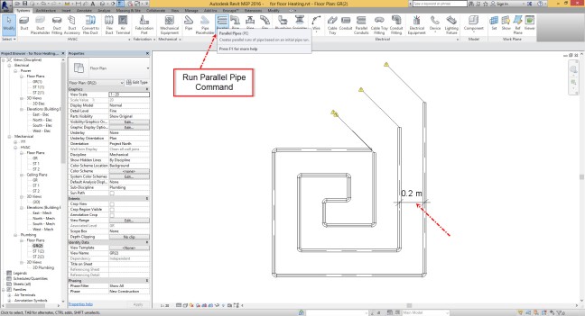
Hi I was a business trip in pas 3 days and now I came back , Lets start new trick

As I said before Sloped Glazing Roof is amazing tool in Revit , then for this trick we want use this command for Stud and panel in the Ceiling System.

I prepared all things you need for this method of Modeling :

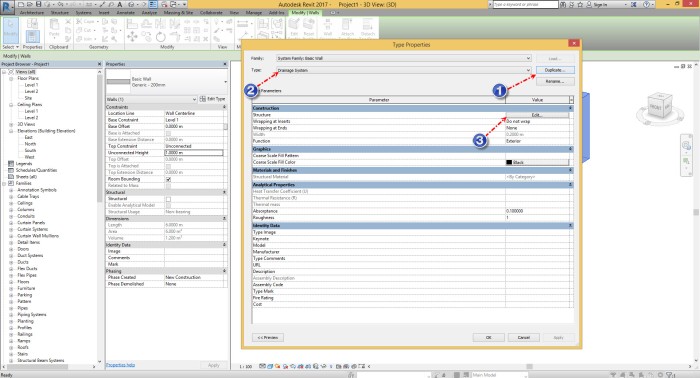
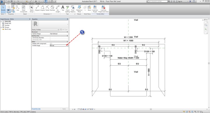
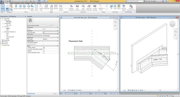
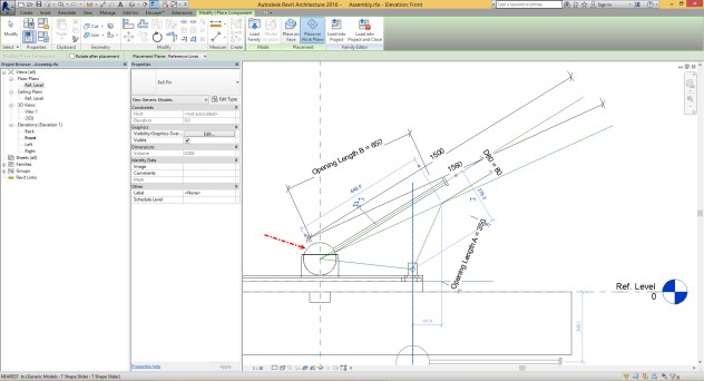
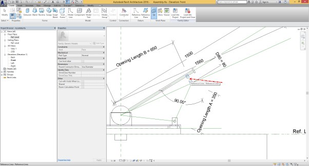
  1. Profile for Stud ( Profile Type : Mullion ) with two Type .

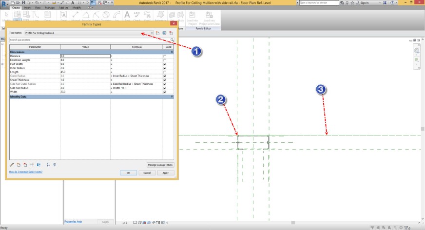
you can see Type A in the below picture and as you can see this profile is connect with the base reference line of Profile Family.


Ceiling 17


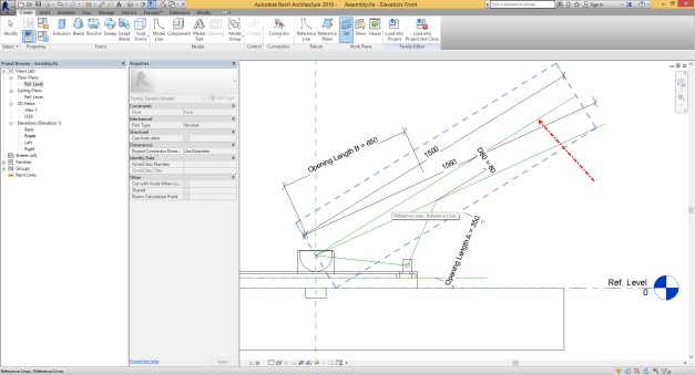
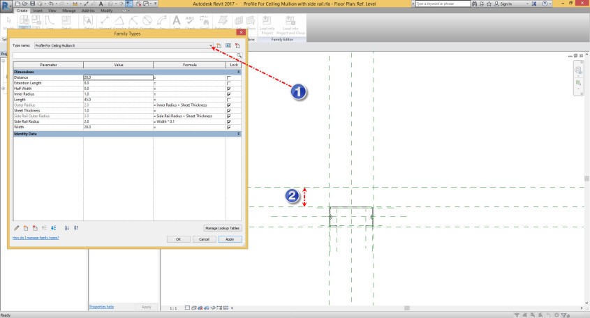
you can see Type B in the below picture and as you can see in the ark ( 2 ) we have distance between Origin and bottom of Profile .

This distance is equal with the Width of the Stud Profile.


Ceiling 18


3.  Load the profile into the Project and use them for new Mullion Type as you can see in the Mark ( 1 , 4 ) and change the Profile family for each of them.

Ceiling 21


4. Another Part is Hanger for Stud. You can use Curtain Wall Panel for this.

Ceiling 19

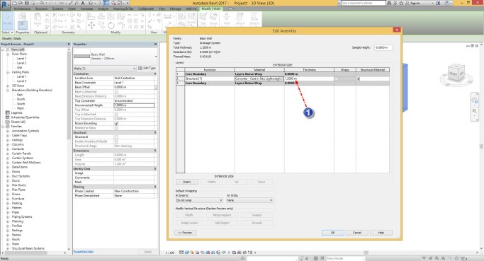
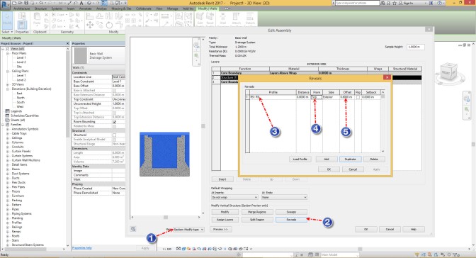
5. Final Part is Plaster board panel and for this part you can make duplicate from solid panel and change the properties for panel like the below picture.

Ceiling 20

After preparation for this parts you need to make four new type in the Roof Sloped Glazing Type .

Type 1 ; Call that Mullion A and change the properties like below picture.

Ceiling 22

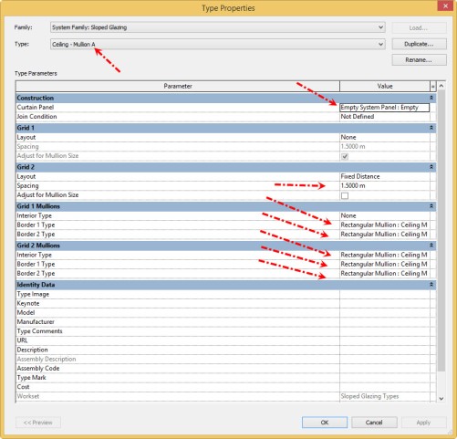
Type 2 : Call that Mullion B and change the properties like below picture.

Ceiling 23

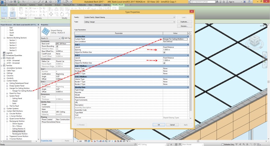
Type 3 : Call that Hanger and change the properties like below picture.

Ceiling 24

Type 4 : Call that Hanger and change the properties like below picture.

Ceiling 25


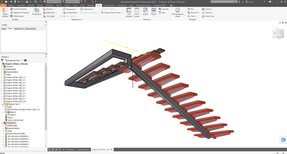
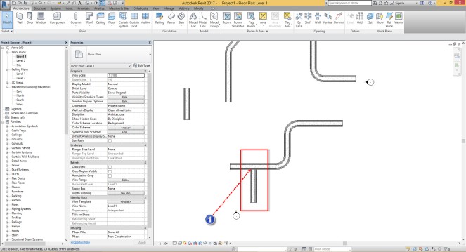
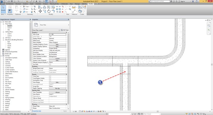
After all preparation you can start with the procedure I will say in the next . I should say at this example I create base ceiling for project before I start to create stud.

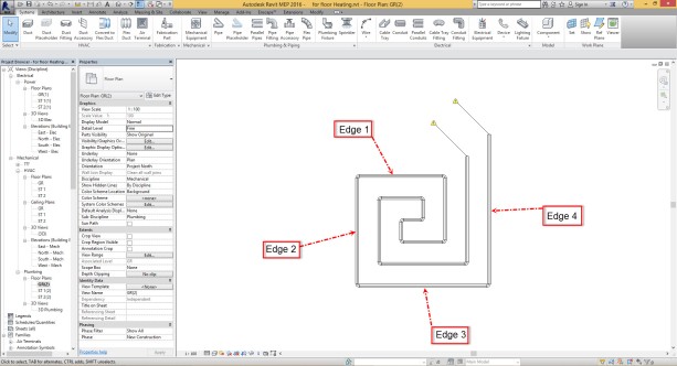
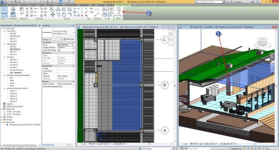
Select the ceiling ( 1 ) and select Edit Boundary ( 2 )

Ceiling 1

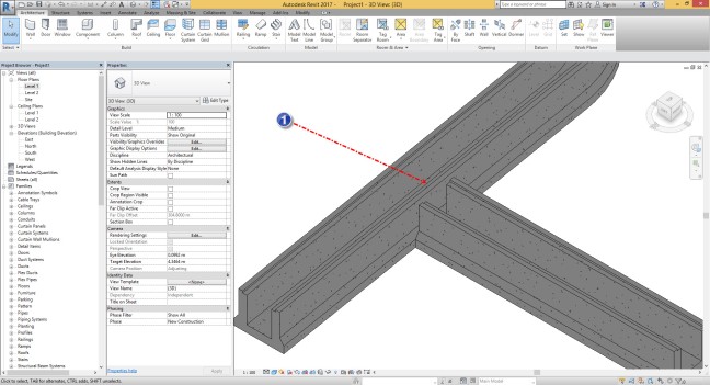
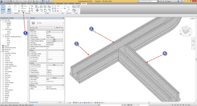
Select all of the boundary line ( 1 ) and select Copy clipboard ( 2 )

Ceiling 2

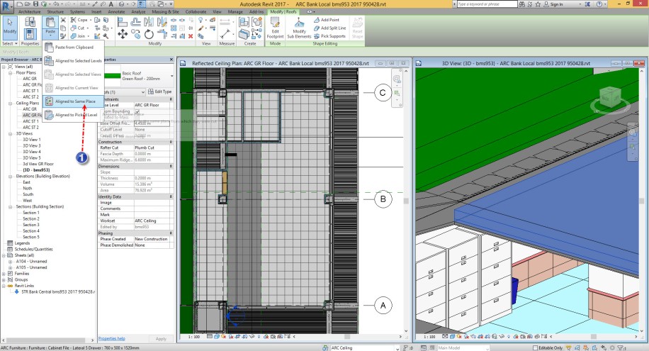
Create new Roof by Footprint ( 1 ) and go to the Past drop down and select align to current view ( 2 )

Ceiling 3

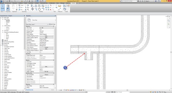
Click on the Finish button , Select the Roof ( 1 ) change the height for placing the roof behind the ceiling ( 2 ) and select Copy clipboard ( 3 )

Ceiling 4

Hit the Align Same Place for 3 time to have 4 Roof in the same Place .


Ceiling 5


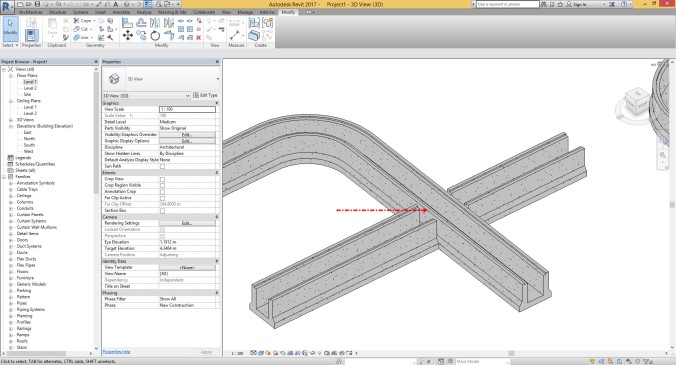
Select one of the Roof and change the type to Mullion A

Ceiling 6

Select another one and change the type to Mullion B

Ceiling 7

Select the third one and change the type to Panel 1.5×3 Meter

Ceiling 8

Select the Final one and change the type to Hanger
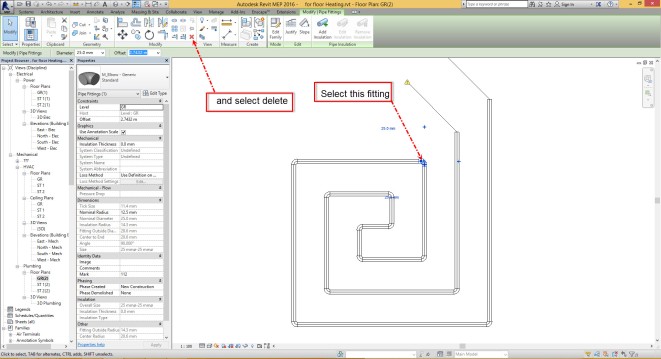
Ceiling 9

Select Delete Type

Ceiling 10

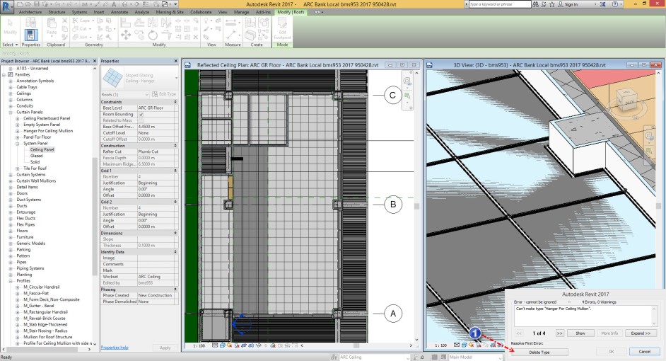
and then Select Replace Type.


Ceiling 11

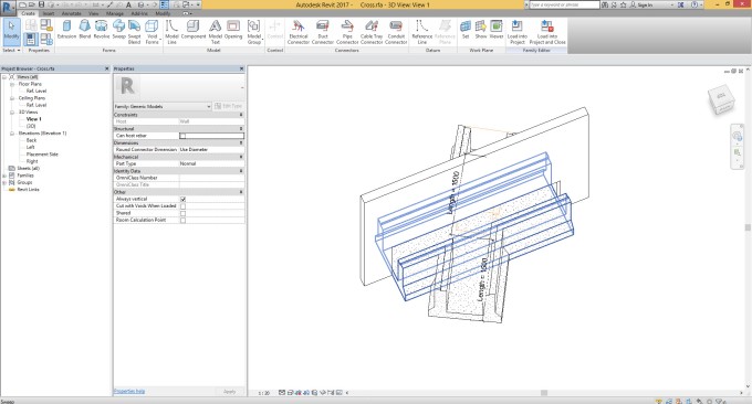
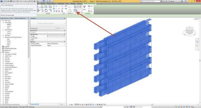
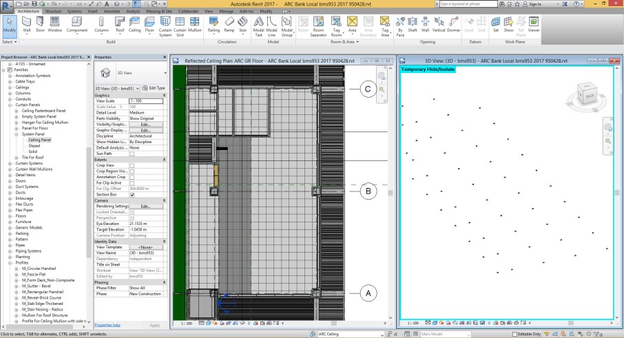
Make your view as Isolated View . ( For selecting this panel I used Single Select method but for big boundary you can use Filter )

Ceiling 12

And change the type to Empty Panel .

Ceiling 13

Like Below Picture.

Ceiling 14


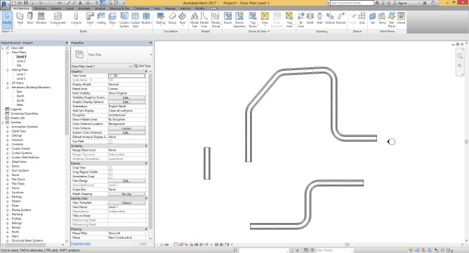
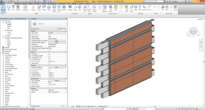
You will see your Stud System perfectly in the Project and other information like the shape of Panel and quantity of Panel.

Ceiling 16


Good Luck.


Quick trick, How you can create boundary for front view of wall when you have Sweep on that ?

Did you ever use Wall Sweep for your Wall in the Project modeling ? You can add many detail into the wall model but you have many limitation with this tool.

For example if you use Wall sweep in the edit structure dialogue then you are able to add many wall sweep simultaneously into the wall and all of them creating automatically , but the problem where coming you want to create schedule from this wall sweep , you are not able to  create schedule for this type of wall sweeps.

But if you use Wall Sweep Command every thing is different , you can create schedule for this but you can’t create many of them simultaneously in the project area.


Other problem for both of them is about the font view of wall , in the normal wall which has not any wall sweep you can use Edit Profile Command for change the boundary of the front view for your wall , but you can’t use Edit Profile Command for this type of Wall !!?! maybe you think you can do this , pay attention what is the result for the final model of wall?? could you cut your sweeps as you want ?? with the shape you want ??


In the Next I will explain how you can solve this problem.

Let’s start, I prefer to you create four wall and use Edit Profile command for them like the below picture as you see every thing is ok.

sweep 1

Then make a copy from them and change the type for this walls to another type which has wall sweep. You can see what happening when you have wall sweep into the wall . every thing is for cutting wall sweep are wrong.

Sweep 2

If you select a Wall for example like the below picture and go to the Edit Profile you can see the boundary line.

Sweep 5

And when you finish Edit profile command if you select the wall and pay attention to the Wall sweep point you can understand what happened . In fact the wall sweeps are finishing in the intersection point between the boundary line and guide line of wall sweeps.

Sweep 6

Go to the Edit structure dialogue and check the wall sweep and option for them like the below pictures.

Sweep 3


Sweep 4

Now we can fix this problem very simple. go to the Model in Place area

Sweep 7


You can choose Generic Model


Sweep 8

Run Opening Command ( 1 ) click on the ok button for choosing host of opening ( 2 ) and select which wall you want ( 3 )

Sweep 9

Create your own area s you want and then press Finish icon.

Sweep 10

Select Finish family too.

Sweep 11

you can watch what is the result for your wall, every thing is ok.

Sweep 12

You can do this as the same way for other walls.

Sweep 13


In fact you can add some parameter for which wall has wall sweep in the Edit dialogue of wall and get the correct result for scheduling sweep material.

Good Luck

How we can create drainage system in Revit ?!?

Ok, I saw many people , who are creating drainage system with model in place tool and in my opinion they are working too much for doing this.

Now I want show you how you can create drainage system more than simple then you can think.

All thing you need is a Wall and a Profile.

Let’s start.

Create New Wall ( 1 ) and go to the Edit Type ( 2 )

Drainage 1

Create Duplicate form the Type and Call that Drainage System

Drainage 2

Make change the Thickness for this wall.

Drainage 3

You will have wall like the below picture.

Drainage 4

Now you need to create a profile for Reveal like the below picture and change the usage to reveal , load this profile into the project area.

Download Family : http://s7.picofile.com/file/8259765142/R9.zip.html

Drainage 5

go to the Edit Type and add Reveal for Wall like the below picture.

Drainage 6

Now you have new Drainage wall in your project and good information then you can use for schedule and you can count your Walls in the project area.

Drainage 7

Go to the plan view and Run the Wall Command , turn on Radius option and change the value for Radius .

Drainage 8

Create your Wall .   What you feeling now ????

Drainage 9

But something is remaining , What happen if you create branch from the main line ?

Drainage 10

Go to the 3d View for recognizing the problem. How we can fix this?!?!

Drainage 11

Drainage system is very similar to Duct system, then we can create some Fitting part for this system and this family can fix the problem for us.

You need to create family like the below picture. the family should be wall based.

http://s6.picofile.com/file/8259765118/WYE_Fitting.zip.html

Drainage 12

Load the family into the project area and place the family in the floor plan view and change the branch angle in the Instance properties dialogue .

Drainage 13

Now you can use Align command for aligning between wall center line and the reference plan of the fitting.

Drainage 14

Go to the 3d View and use join command for joining the family and wall together.

Drainage 15

For cross section you have same problem .

Download family : http://s6.picofile.com/file/8259765100/Cross.zip.html

Drainage 16

And you can use same method .

Drainage 17


Drainage 18


Drainage 19

At the Final you have every thing you want , Fast modeling , Precise schedule , Fast Editing , etc.


Good Luck


Just Experience sharing , Steel Structure Detailing with Autodesk Inventor Professional !?!

I Said before my opinion About the Autodesk Inventor Professional.

Then three or four years ago is start to create my own plugin to build steel structure with Inventor Pro.

And I did some project with this plugin , Autodesk Inventor is very useful and very powerful for modeling.

aa


aaa


I Send This Proposal For AU Las Vegas , but ……

Good Luck.

Ball Constraint ,Slide Constraint , Cylindrical Constraint in Revit !

As I said before I want to show you how you can crate this type of constraint in Revit Like Inventor Professional.

Let Start ,

For this assembly we need six part as you can see in the below picture:

1.Rotter Part

Ball 1

Download Part : http://s6.picofile.com/file/8259515042/Rotter.zip.html

2. T Shape Slider Part

Ball 2

Download Part : http://s6.picofile.com/file/8259515050/T_Shape_Slider.zip.html

3. Ball Pin

Ball 4

Download Part : http://s6.picofile.com/file/8259514942/Ball_Pin.zip.html

4. Pipe Slider Part

Ball 6

Download Part : http://s7.picofile.com/file/8259515018/Pipe_Slider.zip.html

5. Piston Part

Ball 3

Download Part : http://s6.picofile.com/file/8259515026/Piston.zip.html

6. Cylinder Part

Ball 5

Download Part : http://s7.picofile.com/file/8259514992/Cylinder.zip.html

Now we can start our assembly. you need to create new Family and call that Assembly in my opinion Face Base family is prefect . from the Insert Ribbon run the Load Family Command and load all of the part into the assembly family.

Ball 7

  1. place the Rotter family with this option and pay attention to the Reference Line in the mark 2 and 3

Like the below picture you can go to the front view and create new Reference Plan and make align for this reference plan, then you can call that for example a.

Ball 8

Like the below picture create a reference line make align from the start point ( 3) between to reference plan (4 , 5 ) and create an angular dimension between reference line ( 1 ) and reference plan ( 2) create a parameter from this dimension and call that for example Rotor angle

Ball 12

Set the work plan of reference line like to below pictures

Ball 13


Ball 14

Place the T Slider shape component on like the below picture and set the correct position for this part.

Ball 15

Go to 3d View and change the Rotor Angle parameter for test.

Ball 16

Change the work plane to the another work plan of reference line then you draw before and go to the front view.

Ball 17

Ball 18

Ball 19

Run the reference line Command and start to create from the intersection below pictures.

Ball 20

Ball 21

Create three reference line like the below picture.

Ball 22

add some parameter for this reference line , the length for reference line ( 3 ) is fixed and two other parameter are instance.

Ball 23

Change the work plan like the below pictures.

Ball 24

Ball 25

Create new reference line ( 1 ) and add fixed dimension for this reference line , then you need to create dimension depend to the Pipe slider part ( 2 )

Ball 26

change the reference plan like the below pictures.

Ball 27

Ball 28

place the Ball pin part and change the position and orientation like the below picture.

Ball 29

create new reference line  ( 1 ) and then add angular dimension ( 3 ) and make align between the new reference line and the end of reference line ( Opening Length A )

Ball 30

Set the work plan like the below pictures.

Ball 31

Ball 32

Place the pipe slider part and change the position and orientation like the below picture.

Ball 33

Set the work plan like the below pictures.

Ball 34

Ball 35

Place the Piston part and change the position and orientation like the below picture.

Ball 36

Create new Reference Line Like the below picture and set the Work plan.

Ball 37

Ball 38

Now you can place the Cylinder part and change the position and orientation for this part like the below picture.

Ball 39

Go to 3d View and change the parameter for test .

Ball 40

Download Family : http://s6.picofile.com/file/8259515050/T_Shape_Slider.zip.html


Now you have Ball constraint in Ball pin Part and housing of Rotor Part , Slide Constraint between Ball pin Part and Pipe Slider Part and two concentric Constraint for Piston and Cylinder Part.

Good Luck.


Quick Trick , Create pipe loop for Floor Heating system!!!

When I was teaching Revit MEP to a Consultant in Iran they ask me about the Floor Heating System and they want to know how we can do this very fast in Revit , first of all I should say the piping shape for floor heating is various and in fact it’s depend to the Plan of the building.

but in many situation you need to create something like the title picture and this is very simple in Revit.

First step is about one Circulation of Pipe like the below picture. We need to the four edge for create this pipe system and as you see in the picture we have four pipe segments for four edges.

Floor Heating 1

After you create the first loop of pipe now you need to select the fitting and delete it, because you should break the chain of the pipe at here.

Floor Heating 2

After that you need to pay attention to the distance between parallel pipe like the below picture and run the Parallel Pipe Command from the System Ribbon.

Floor Heating 3

Put the Dimension as you need for example 10 for Horizontal Number and 0.2 m for distance .

Floor Heating 4

Put your courser over the one segment of pipe loop , as you see in the below picture and press TAB key from your keyboard for one time, you can see the guide line for duplicate of pipes.

Floor Heating 5

Press Left click from your mouse and you can get the below picture.

Floor Heating 6

The Final step is very simple , all thing you need is Trim to Corner command and you need to trim the pipe segments as I mark in the below picture on after the other .

Floor Heating 7

Final Result is what you want and this method is very fast for modeling.

Floor Heating 8


Good Luck.

Ramp with Detail and Finishing Layer in Revit ?

From the first time I start to use Ramp command in Revit I find many issue for this tool and now after eleven years we don’t have any improvements for this command , now I want to show you how we can create Ramp with all detail then we need !? is this possible ? yes , very simple .

Let’s start , first step is about the creating normal Ramp as usual like the below picture


Ramp With detail 1

Then you can turn of the Railing Category for floor plan , because you need to select the boundary of Ramp.

Ramp With detail 2

Now start to create Floor , but Floor type name should contain (( Ramp )) . when you want create the boundary for ramp be careful and use pick line tool with turn on Lock option in the Option bar.

Ramp With detail 3

After you select the boundary line if you select all of the projection line like the below picture then you will have Break point like the picture.

Ramp With detail 4

Go to the 3D View , select the floor and then run Modify sub element tools.

Ramp With detail 6

Change the Elevation parameter Like the below picture ( if you need to find Height for Landing you can try to change single border elevation with click and drag and you can see how single edge can match with the Landing Border and you can find the Elevation )

Ramp With detail 7

For the Final step you can do same method for Single border line with click and drag. below picture

Ramp With detail 8

In fact now you have a ramp with detail in the Finishing Layer but you need change something for present this Ramp in the Section view. So , you can turn off ramp category for all of the Section views.

Ramp With detail 9

For floor plan you need to create a Filter like the below picture .

Ramp With detail 10

And you can see everything is ok in the Floor Plan.

Ramp With detail 11

But something is missing here !?! What about the Solid Ramp ?!? how we can do this with floor ?!?!

Ramp With detail 12

Go to the Edit Structure dialogue and make the check box on for Variable option.

Ramp With detail 13

Now You have solid Ramp in Revit


Ramp With detail 14

Ramp With detail 15

And one thing remain, What about the Arc Shape Ramp ?!?!

Ramp With detail 16

You can use the same method and Revit can create everything Automatically , and you can see all of the border line are aligned with the Normal Ramp.

Ramp With detail 17

Ramp With detail 18

And for the Final Part you can add some Cut family over the finishing face of the Ramp.

Ramp With detail


Good Luck.


How we can create good presentation in Revit for Wall , Floor , Roof or Ceiling

(( At first i should say for this post i use WFRC except Wall , Floor , Roof , Ceiling. ))

I saw lot of people who want have good presentation in Revit for WFRC.

Many of them are using Create Part Command and some times Model in Place or some sort of family combination.

Presentation 1


But the question is what is the ability for each one of this method. If you use Create Part command you can get presentation over the project model .

Presentation 3

For example you can select Wall from the project and isolate that part and then convert the Isolate view to Hide view.

Presentation 2

Now you can Create your own presentation with Create Part Command ( This ability is very good because you can create presentation on the one segments of the project model ) After that you have many ability like show shape Handles , Divide Part , Exclude Division Profile and etc.

Presentation 4

But you have a lot of limitation in create part tool , for example all of the parts then coming from the base objects WFRC are box shape and for good presentation you need more detail much as box shape.

What about the Model in Place or some sort of Family combination?!?! This item can produce better shape buuut you miss all of ability then you have in Create Part Command (( show shape Handles , Divide Part , Exclude Division Profile and etc. ))

What about the combination of this two method ?!?!

The Method then I want to show you is very simple and you can use this method in which segments of your project model very simple . Every thing you need is some type of family for combine with WFRC category.

Page 8

First Example is the top picture , for this wall you need family like the below pictures

Presentation 5

Brick Pattern Family with void, the void should be combine with the host object and cover all of the Brick Pattern as you see in the picture.

You can Download this family from here :  http://s6.picofile.com/file/8259246826/Block_Pattern.zip.html

Presentation 6

Next Family is the top picture and this is for cutting the exterior layer of the Wall.

You can Download this family from here : http://s6.picofile.com/file/8259246950/Cut_For_Exterior_Stone_Pattern.zip.html

Presentation 7

Next Family is the top picture and this is for cutting in the  Interior layer of the Wall or for Floor Tile.

You can Download this family from here : http://s7.picofile.com/file/8259247468/Wall_and_Tile_Cut_Present_Pattern.zip.html

Presentation 8

Now you have base wall and you can start to place your family on the wall.

Presentation 8 a

And after that you need to use Cut command for combine family with wall like below picture

Presentation 8 b

The next step is for Interior side and you can see is the same as exterior side.

Presentation 9

Rebar Cover 9 a

Final Step for placement is Brick Pattern but you need to use Tab Key on your keyboard for select correct face for this family , because you need to place this family on the face of structure layer.

Presentation 10

Now you can see this shape in your project  area and in fact you combined the family with WFRC category with this method.

Presentation 10 a

Final step is Create Part Command and now you have all ability for this method

Presentation 10 b

Project File : http://s7.picofile.com/file/8259249842/Page_7_Wall_Presentation.zip.html

You can see Floor Presentation in the below picture for KSD Structure Floor and Finishing layer as Tile.

Presentation 12

you can download floor presentation file from here :

http://s6.picofile.com/file/8259250092/Page_7_Floor_Presentation.zip.html


Good Luck.